Extending on-premises VLANs with VyOS from VMware vSphere to Nutanix Cloud Clusters
When migrating workloads from on-premises to the cloud it is often desireable to minimize downtime. In this example we show how to migrate VMs with continuous network connectivity and no IP changes. We achieve this by extending an on-premises VLAN to NC2 on AWS using VyOS, thereby ensuring that VMs which have already been migrated and VMs still on-premises can stay in touch during the migration process. Think of it as stretching your on-premises networks to the migration destination - in this case AWS. Thereby your VMs will have the "same" network both in your physical DC and in the cloud.
Why extend networks to the cloud?
Very often those who want to migrate from their on-premises datacenters to the cloud wish to do so with minimal disruption. Both to the workloads / VMs themselves but also to services relying on those workloads as well as end users and application owners. Two points almost always come up:
- How can we migrate without changing the IP addresses of the VMs?
- How can we maintain network connectivity during the migration process?
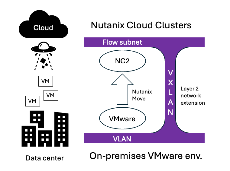
The answer to the first question is: Use Nutanix Move. Move can migrate from VMware on-prem (and from VMware Cloud on AWS) to NC2 on AWS. Also, despite being a very powerful migration tool, it is available to Nutanix customers free of charge.
The answer to the second question is: Stretch your on-premises networks to the cloud during the migration process. Ideally, switch the networks over to the cloud after migration is complete. This is done using Layer 2 extension (L2E) and the Nutanix-side of this feature is included with Nutanix Flow.
Solution architecture
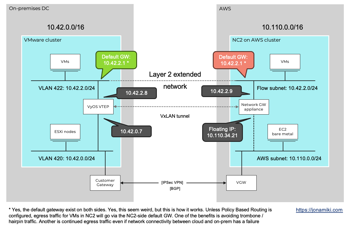
Below is a diagram showing what components are involved and how they are connected. On the right hand side we have the NC2 on AWS cluster. We have used Flow Virtual Networking (FVN) to create a NAT overlay subnet. NAT overlay basically means that it exists in NC2 but is NAT:ed and therefore invisible from the AWS native VPC side.
Flow allows us to create subnets with any CIDR range, completely independent from the AWS native network side. These networks can still communicate with the outside world (and with each other, as long as the network ranges don’t overlap). We use this to our advantage when we migrate as we can do a 1:1 match of the on-premises networks on top of NC2.
When we then migrate, Nutanix Move will retain the original IP addresses and plug in the VMs into the Flow overlay equivalent of their on-premises subnets post migration.
Overview of steps
It is quite straight forward to set up and migrate with layer-2 stretch. We assume there is already an NC2 cluster deployed on AWS and that there is IP reachability between on-premises and the NC2 cluster. In other words, there is a DirectConnect connection or a Site-2-site VPN configured and you can ping between NC2 to the on-prem VMware cluster. For our example we go through the following setup steps to get our environment up and running:
- On the NC2 cluster, create a Flow VPC - Yes, this is a Nutanix Flow VPC and not AWS VPC :)
- In the Flow VPC, create a subnet with the same CIDR range as the on-premises VLAN
- Deploy the Network Gateway appliance and attach it to the Flow VPC
- On the on-premises VMware environment: Download and deploy VyOS
- Enable Promiscuous mode and Forged transmits on the vSwitch portgroup of the VLAN to be extended
- Configure the VyOS network interfaces:
- Create a VxLAN interface and add it together with the interface on the network to be extended to a bridge
- On NC2 on AWS: Extend the network
Environment
In this example we use the below software versions and networks
| Entity | Version |
|---|---|
| NC2 on AWS Prism Central | pc.2024.3 |
| NC2 on AWS AOS | 7.0 |
| On-premises vCenter | 7.0u3 |
| On-premises VyOS | 2025.03.12-1116-rolling |
| Entity | Value |
|---|---|
| On-premises CIDR | 10.42.0.0/16 |
| AWS VPC CIDR | 10.110.0.0/16 |
| On-premises underlay VLAN | VL 420 (10.42.0.0/24) |
| On-premises extended VLAN | VL 422 (10.42.2.0/24) |
Step 1: Create the Flow VPC
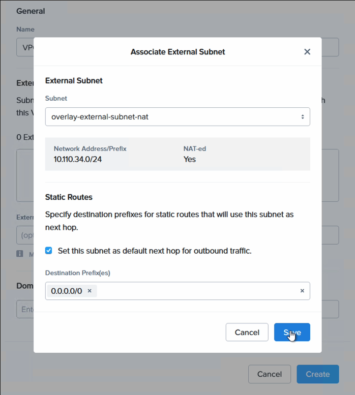
This is a 30 second job. The VPC is essentially a container for networks, just like the AWS VPC. For external connectivity, please use a NAT subnet as in this example. This subnet will be automatically created if Flow was selected to be deployed as part of the cluster deployment. If not, please create a Transit VPC and a NAT subnet to use for external connectivity. Note that to stretch a subnet, the VPC it resides in must have a NAT network set for external connectivity.
| Entity | Value |
|---|---|
| Name | VPC A |
| External connectivity | overlay-external-subnet-nat |
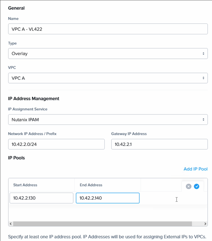
Step 2: Create the Flow subnet
We create the subnet in our newly created Flow VPC. Match the CIDR range and default gateway with the on-premises network, but set the DHCP range to not overlap with on-prem DHCP or static IP addresses.
| Entity | On-prem value | Value in NC2 |
|---|---|---|
| Extended network CIDR | 10.42.2.0/24 | 10.42.2.0/24 |
| Extended network GW | 10.42.2.1 | 10.42.2.1 |
| Extended network DHCP | 10.42.2.20-99 | 10.42.2.130-140 |
| Value of Pi | 3.1415926535 | 3.1415926535 |
| Level of awesomeness | 3 | 5 |
Step 3: Deploy the Network Gateway appliance
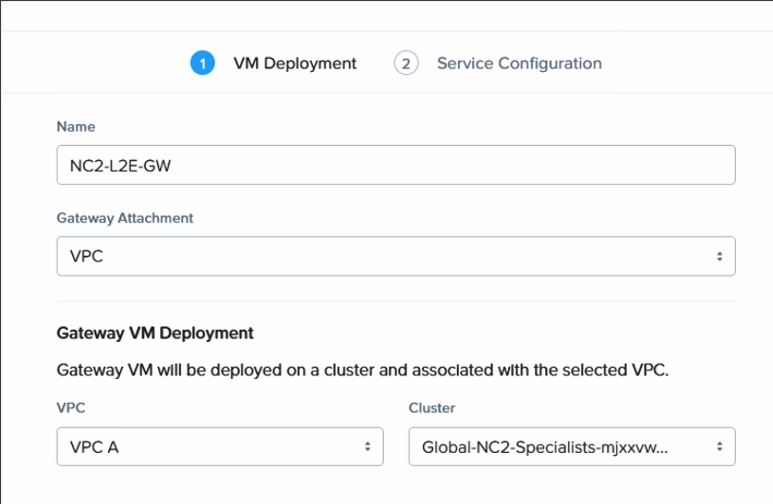
This is also a very simple process. In Prism Central in NC2 on AWS, simply navigate to Connectivity and deploy a new Local Gateway. Select VPC and the VPC we just created in step 1. The Network Gateway appliance with receive a floating IP from the AWS VPC range. We use it later as the underlay (routed) network anchor point to connect with VyOS on-prem
| Entity | Value |
|---|---|
| Name | Anything you want |
| GW attachment | VPC |
| VPC name | VPC created in Step 1 |
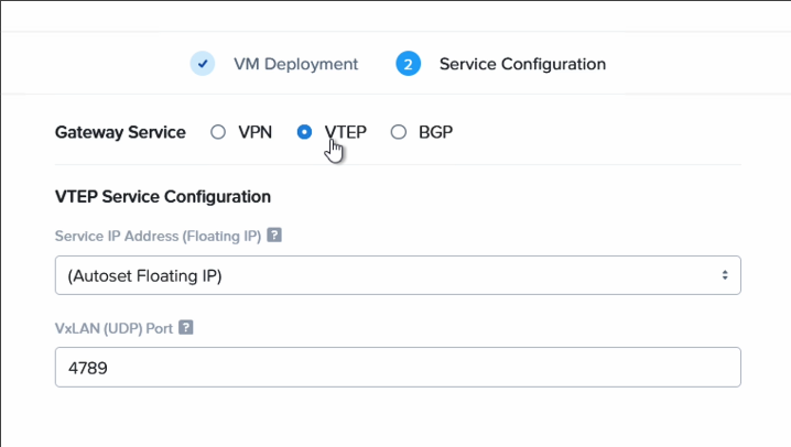
| Gateway Service | VTEP |
| VxLAN port | 4789 (default) |
VM Deployment
Service Configuration
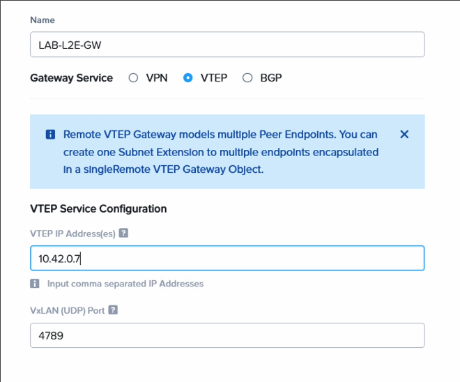
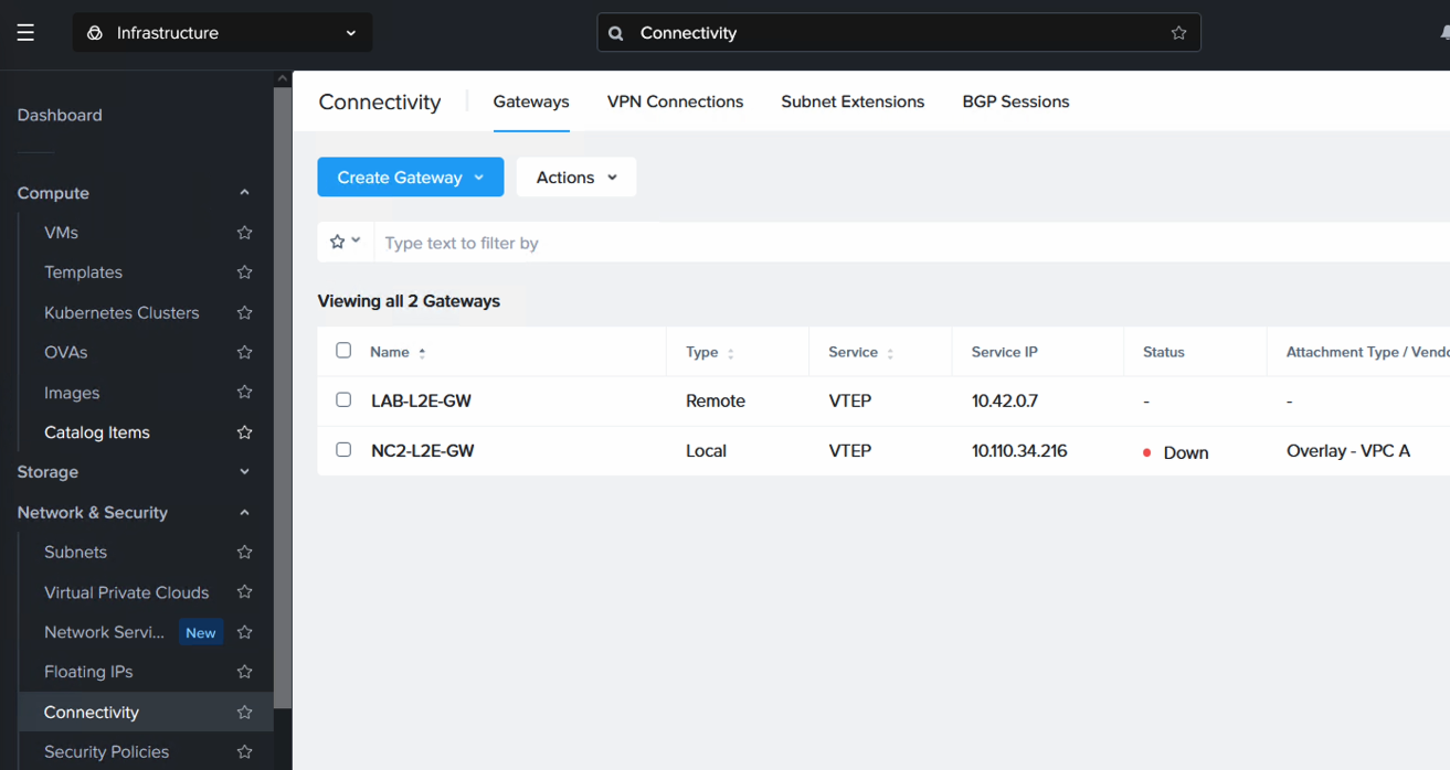
Also register the remote VTEP gateway IP. Nothing is deployed on NC2 for this, it is only a pointer to the on-premises VyOS appliance IP address. Navigate to “Network & Security”, “Connectivity” and select “Remote” from the “Create Gateway” drop-down menu.
| Entity | Value |
|---|---|
| Name | Anything you want |
| GW service | VTEP |
| VTEP IP | Your on-prem VyOS eth0 IP |
| VxLAN port | 4789 (default) |
Step 4: Download and Deploy VyOS
There is a quick guide here on how to deploy the free version of the VyOS appliance on VMware vSphere in preparation for this blog post. Pleae refer to it for detailed steps.
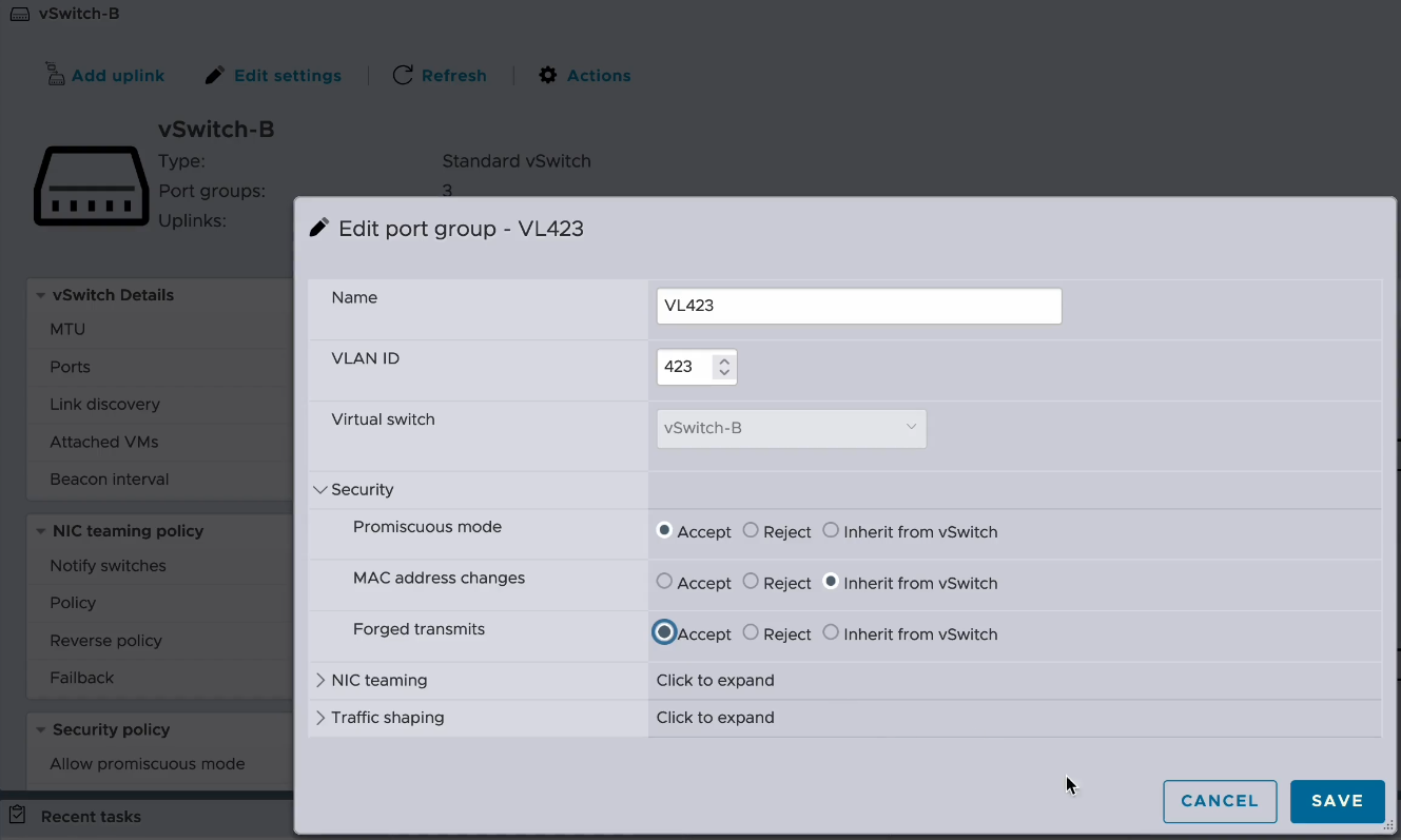
Step 5: Enable Promiscuous mode and Forged transmits on the vSwitch portgroup of the VLAN to be extended
In order to pass traffic from the on-premises network to the NC2 network it is necessary to enable Promiscuous mode and Forged transmits on the vSwitch port group on the VMware cluster. In this case we are using standard vSwitches.
Step 6: Configure the VyOS network interfaces
If you have followed the guide on Downloading and Deploying VyOS in the previous step, you have likely already configured SSH access and thereby also the IP address for the interface attached to the underlay network. If not, use the vCenter or ESXi console viewer to set the IP.
| Entity | Value |
|---|---|
| eth0 IP (underlay interface) | 10.42.0.7 |
| Default GW | 10.42.0.1 |
| eth1 IP (extended network interface) | not set |
| eth0 MTU | 1454 |
Setting the underlay / routed IP address + enabling SSH
1
2
3
conf
set interfaces ethernet eth0 address 10.42.0.7/24
set service ssh
Configuring the default route and DNS for the VyOS appliance
1
2
3
4
[edit]
vyos@vyos# set protocols static route 0.0.0.0/0 next-hop 10.42.0.1
[edit]
vyos@vyos# set system name-server 192.168.0.10
Setting the MTU and descriptions for our interfaces
Note that the MTU will vary depending on your connectivity to the cloud. Four our VPN we allow for the VPN encapsulation by lowering the MTU to 1454. You may need to lower it further or set it to a different value altoghether depending on your environment.
1
2
3
4
5
6
[edit]
vyos@vyos# set interfaces ethernet eth0 mtu 1454
[edit]
vyos@vyos# set interfaces ethernet eth0 description "VL420"
[edit]
vyos@vyos# set interfaces ethernet eth1 description "VL422"
Step 7: Create a VxLAN interface and add it together with the interface on the network to be extended to a bridge
| Entity | Value |
|---|---|
| VxLAN Network Identifier (VNI) | 1 to 16777215 (we match the VLAN ID: 422) |
| Bridge IP (on the extended network) | 10.42.2.8 |
| VxLAN remote IP (NC2 Network GW floating IP) | 10.110.34.216 |
| eth1 adjust-mss (MTU) | 1360 |
Setting the VxLAN port, VNI and source IP
The source IP is the IP address we’ll use to send traffic through the VxLAN tunnel to the AWS endpoint. Therefore we set this IP to match the eth0 IP, as eth0 is our underlay interface. The VxLAN port need to match what we set when creating the Network Gateway in Step 3. We will use the VNI later when extending the network from the NC2 side.
1
2
3
4
5
6
7
[edit]
vyos@vyos# set interfaces vxlan vxlan1 port "4789"
[edit]
vyos@vyos# set interfaces vxlan vxlan1 source-address "10.42.0.7"
[edit]
vyos@vyos# set interfaces vxlan vxlan1 vni "422"
[edit]
Setting the bridge settings and registering the remote VxLAN endpoint (the NC2 network GW floating IP)
After the Network GW appliance has been deployed in Step 3, make note of the floating IP it has been assigned. This IP will be used here as the vxlan1 remote IP. Note that we also adjust the Maximum Segment Size (MSS) to 1360 on eth1, preventing fragmentation in VPN or tunneled traffic.
Checking the NC2 Network GW floating IP
The bridge br1 address is any free IP on the network to be extended. We will be assigning this IP to the NC2 side Network GW when extending the network in Step 7.
1
2
3
4
5
6
7
8
9
10
11
12
13
14
15
16
[edit]
vyos@vyos# set interfaces bridge br1 member interface eth1
[edit]
vyos@vyos# set interfaces bridge br1 member interface vxlan1
[edit]
vyos@vyos# set interfaces bridge br1 address 10.42.2.8/24
[edit]
vyos@vyos# set interfaces vxlan vxlan1 remote "10.110.34.216"
[edit]
vyos@vyos# set interfaces ethernet eth1 ip adjust-mss 1360
[edit]
vyos@vyos# commit
[edit]
vyos@vyos# save
[edit]
vyos@vyos# exit
Viewing the interfaces
With this our VyOS configuration is complete. All that is left is to extend the network from the NC2 side. If we check our interface configuration we can see the IP addresses and MTU assigned to each. Remember to commit, save and exit the configuration mode before issuing the “show interfaces” command:
1
2
3
4
5
6
7
8
9
10
11
vyos@vyos:~$ show interfaces
Codes: S - State, L - Link, u - Up, D - Down, A - Admin Down
Interface    IP Address    MAC                VRF        MTU  S/L    Description
-----------  ------------  -----------------  -------  -----  -----  -------------
br1          10.42.2.8/24  e6:48:d3:5b:57:10  default   1500  u/u
eth0         10.42.0.7/24  00:50:56:82:40:ae  default   1454  u/u    VL420
eth1         -             00:50:56:82:1a:a7  default   1500  u/u    VL422
lo           127.0.0.1/8   00:00:00:00:00:00  default  65536  u/u
             ::1/128
vxlan1       -             f6:71:4e:a5:00:62  default   1500  u/u
vyos@vyos:~$
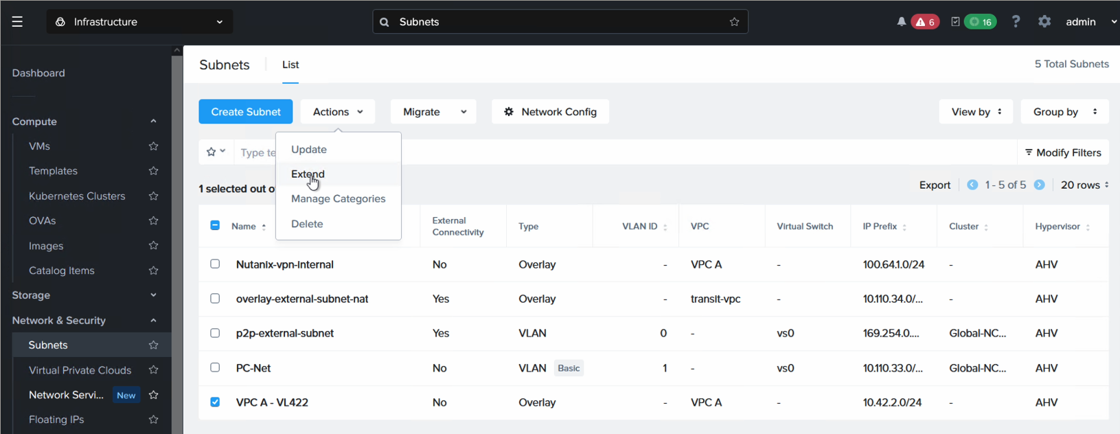
Step 8: Extend the network
This step is performed from Prism Central in NC2 on AWS. Navigate to “Network & Security”, “Subnets”, highlight the subnet to be extended and select “Extend” from the “Actions” drop-down.
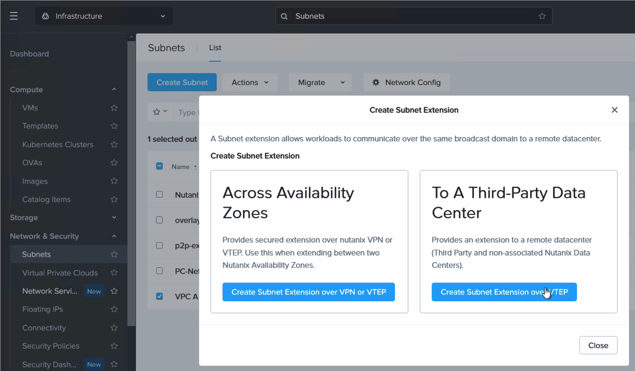
Since we’re extending a network from a non-Nutanix environment, select “3rd party datacenter”
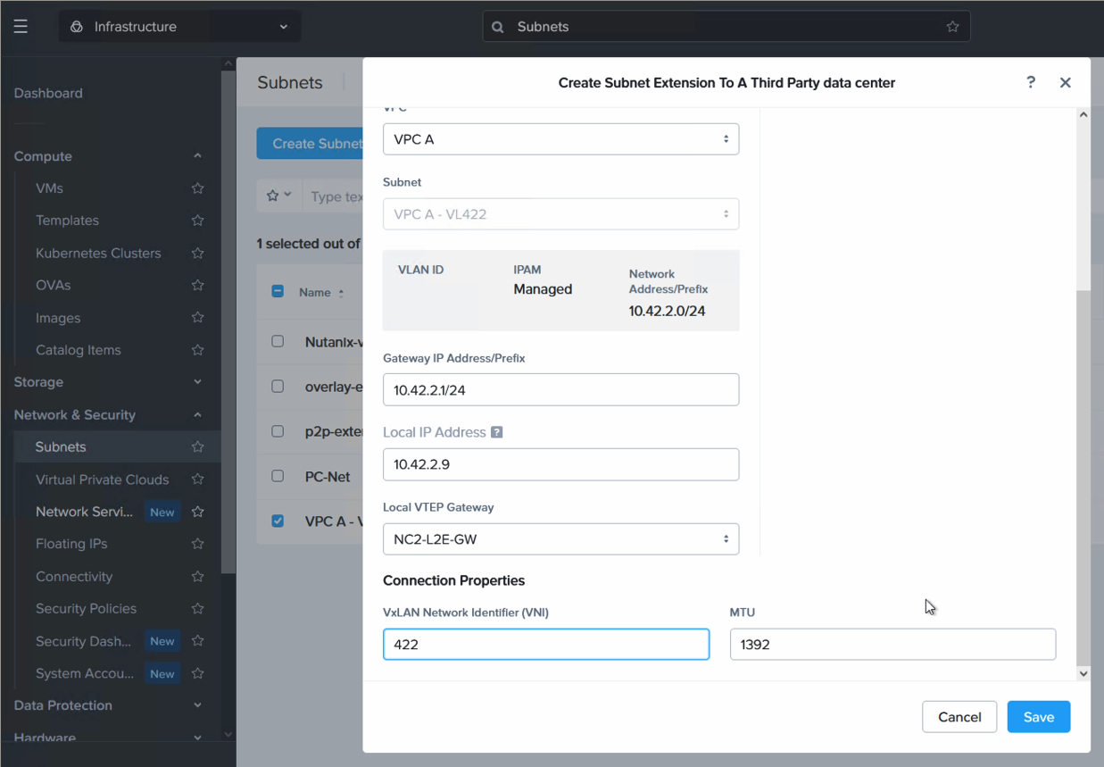
Most of the settings will be pre-populated. For Local IP address, please enter an unused IP outside of the DHCP range on the network to be extended. For VNI we enter the same VxLAN network identifier we set on VyOS previously. In our example it is 422.
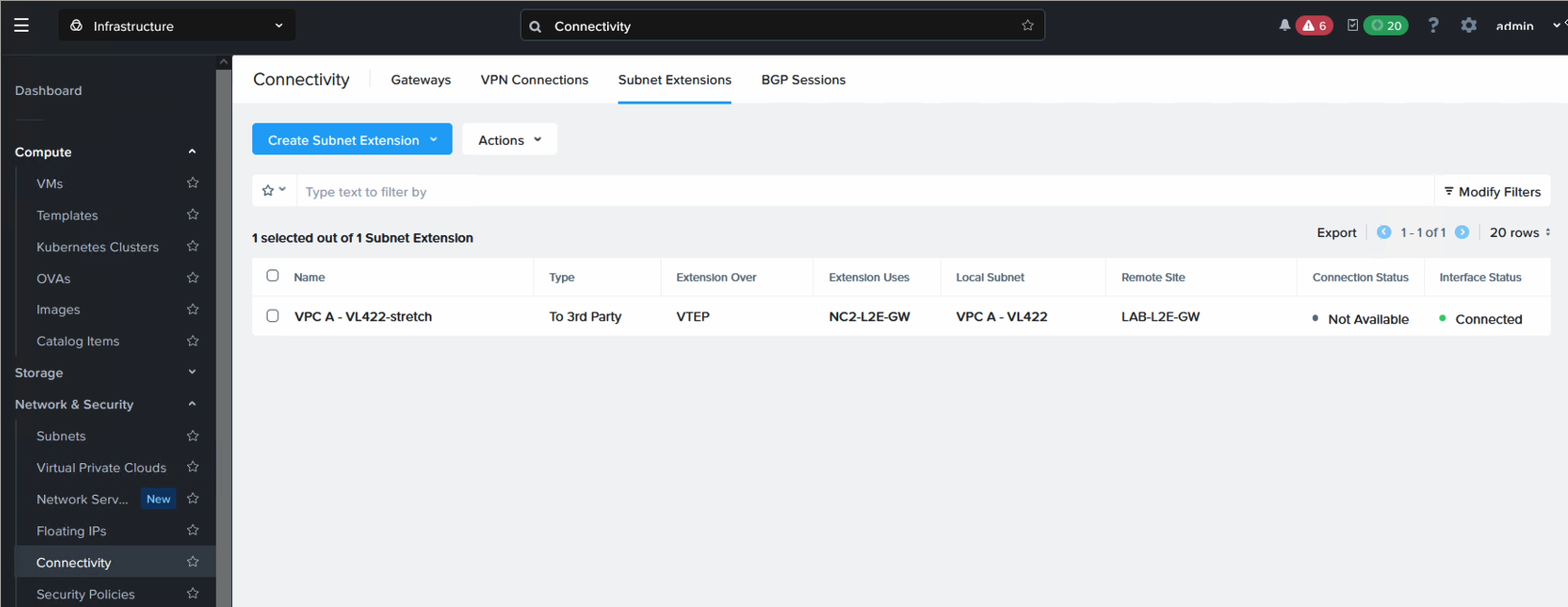
Verifying the network extension
From the Prism Central in NC2 on AWS, navigate to “Network & Security”, “Connectivity” and select the “Subnet Extensions” tab. In here the layer 2 streched network will show up. The interface status should show “Connected” as per the below:
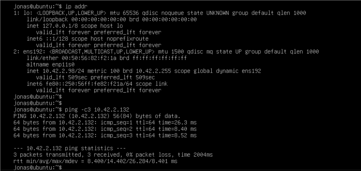
If we deploy a VM on the NC2 side (or better - migrate a VM there from on-premises VMware), we can ping to verify that the layer-2 extension is working. In this case the Ubuntu VM is on VMware, connected to the stretched network with IP 10.42.2.98 and pinging a VM on NC2 on AWS with the IP 10.42.2.132. All is working prefectly fine and our L2 extension has been successful.
Conclusion
This concludes the configuration of Layer 2 extension between on-premises VMware and Nutanix Cloud Clusters on AWS using VyOS as VxLAN VTEP. Hopefully it was helpful. For the full configuration used, please click here.