
There are many cool custom keyboard builds and I wanted to give it a go. This will document the process, parts and steps.
Part list
Some parts can be purchased and some are 3D printed. I printed these at home but there are places to order 3D printed parts from as well
- 3D printed keyboard body (downloaded from Thingiverse or for the brave, generated)
- Arduino Pro Micro x2
- Keycaps
- Key switches
- 3.5mm audio jack part x2
- 3.5mm audio cable
- Micro-USB to USB-A cable
- Diodes (1 / key) model 1N4148
- Copper wire (I used 22AWG with a few different colors for easy separation)
- XH connectors (to avoid soldering directly onto the pins of the Arduino)
- Screws or M3 self-tapping inserts to attach the under plate
- Model paint
Tools used
- Soldering iron
- Solder
- Flux (really important for clean soldering joints)
- Mechanical helping arms
- Razor knife
- Wire stripper
- Black marker
- XH connector crimping tool (I use an IWISS SN-2549)
- 3D printer (if you want to print yourself)
- Breadboard (for testing and as a jig for soldering the Arduino pins)
3D printing the keyboard body
The STL files for 3D printing the body and covers underneath can be found on Thingiverse here: https://www.thingiverse.com/thing:2666676
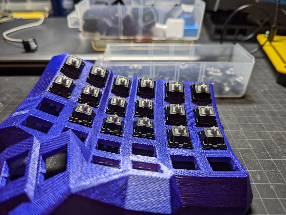
I printed in white PLA using the 0.2mm quality preset on a Prusa i3 MK3s
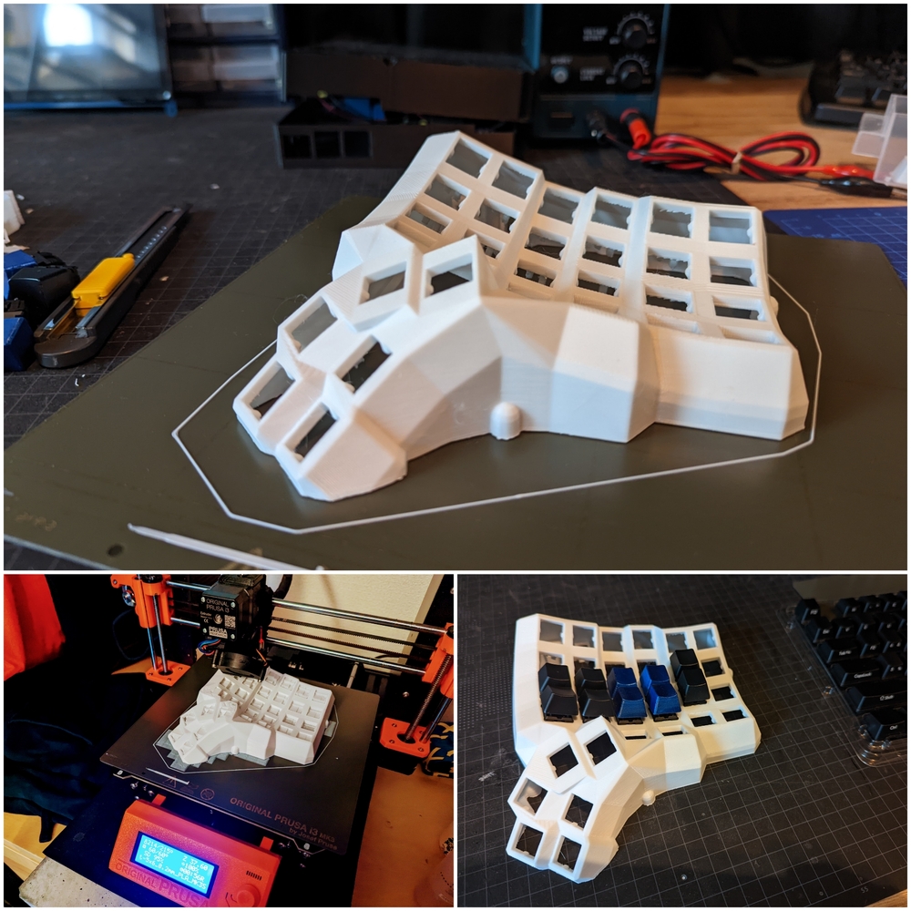
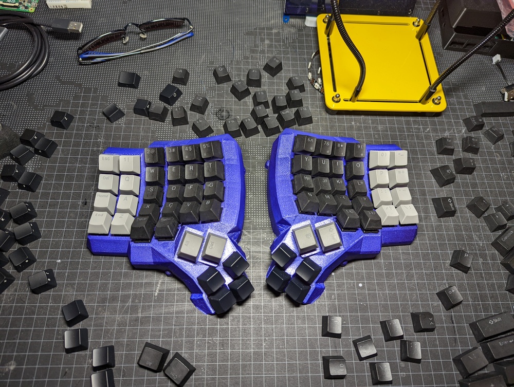
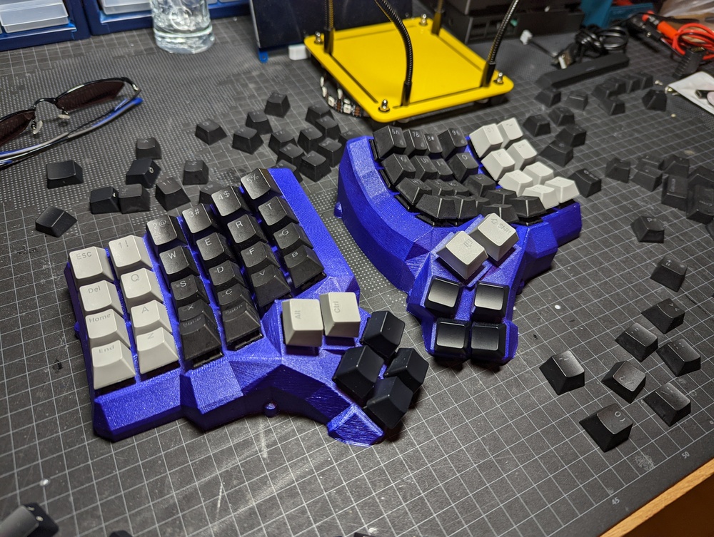
Trying out the fit of a few silver cherry compatible switches after having painted purple using Tamiya TS-24 model paint
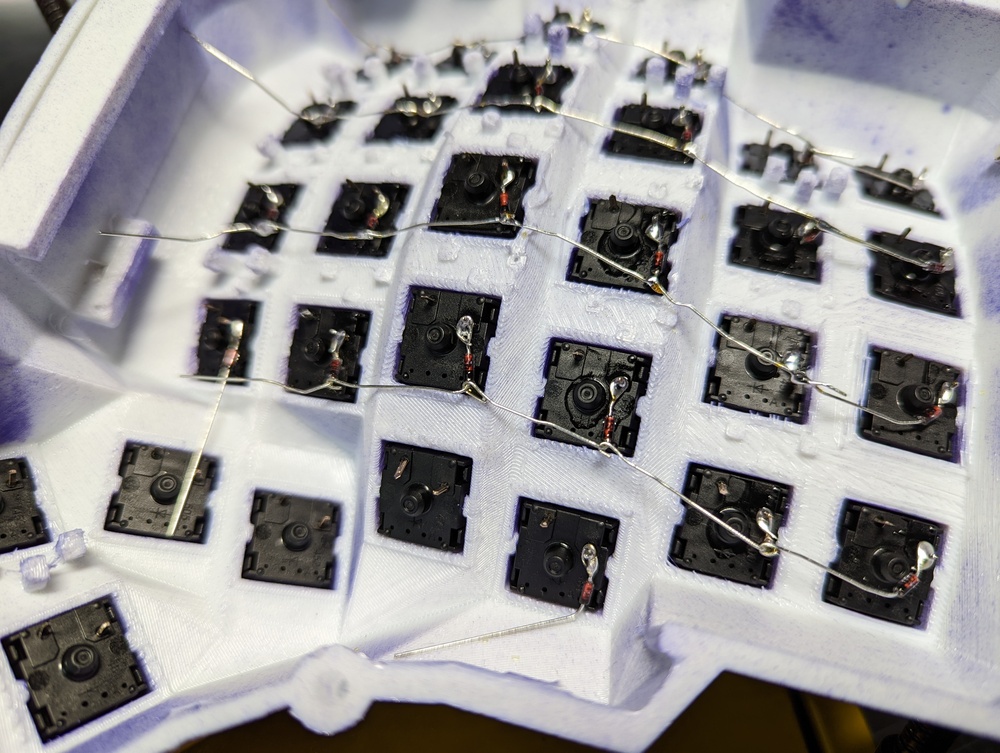
Soldering the diodes
For the wiring I used the diagram by Nick Green shown here.

For each row I use the diodes own wires as connectors between the keys. Solder the brown side of the diode to the key and use the black-side wire to hook up to the next key.
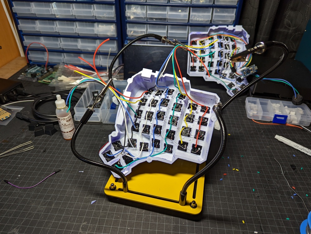
Soldering the vertical connectors
To connect the keys on the vertical side I use AWG22 copper wire with different colors to keep them separate more easily. AWG24 might have been better but this is what I had available at home.
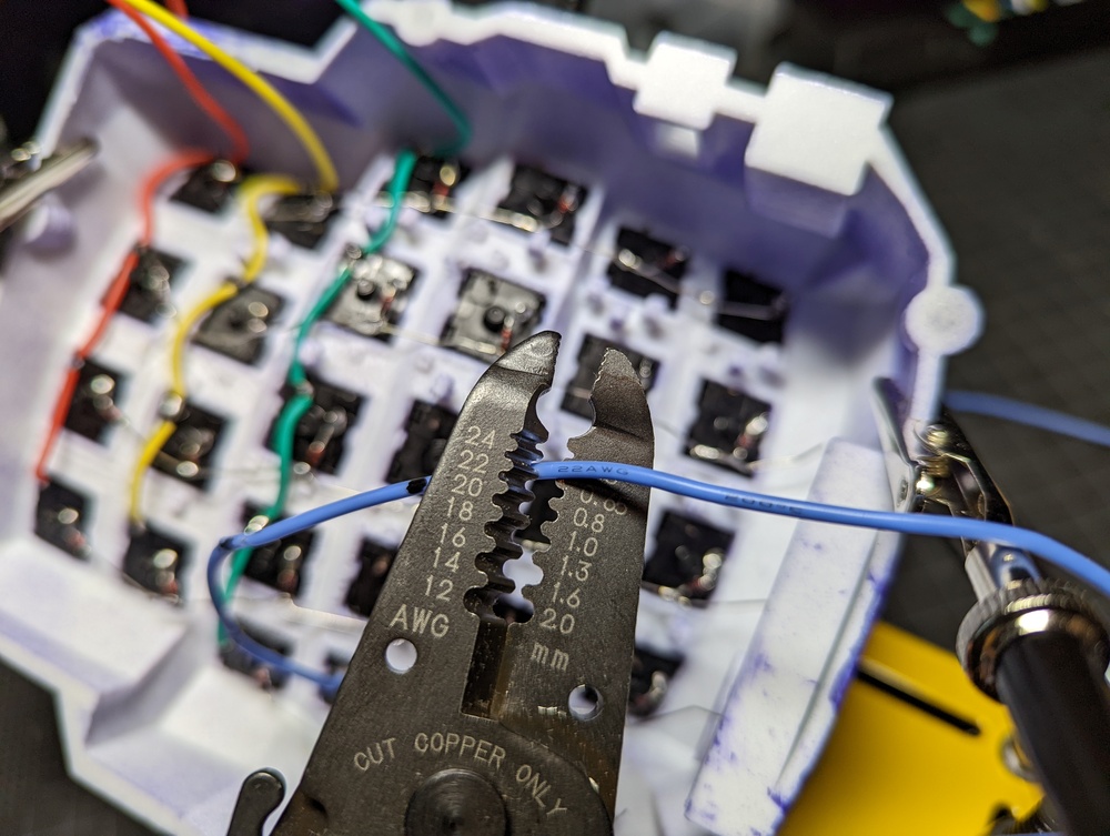
I start by laying out the wire over the keys and then using a permanent marker to mark where they should have the insulation removed
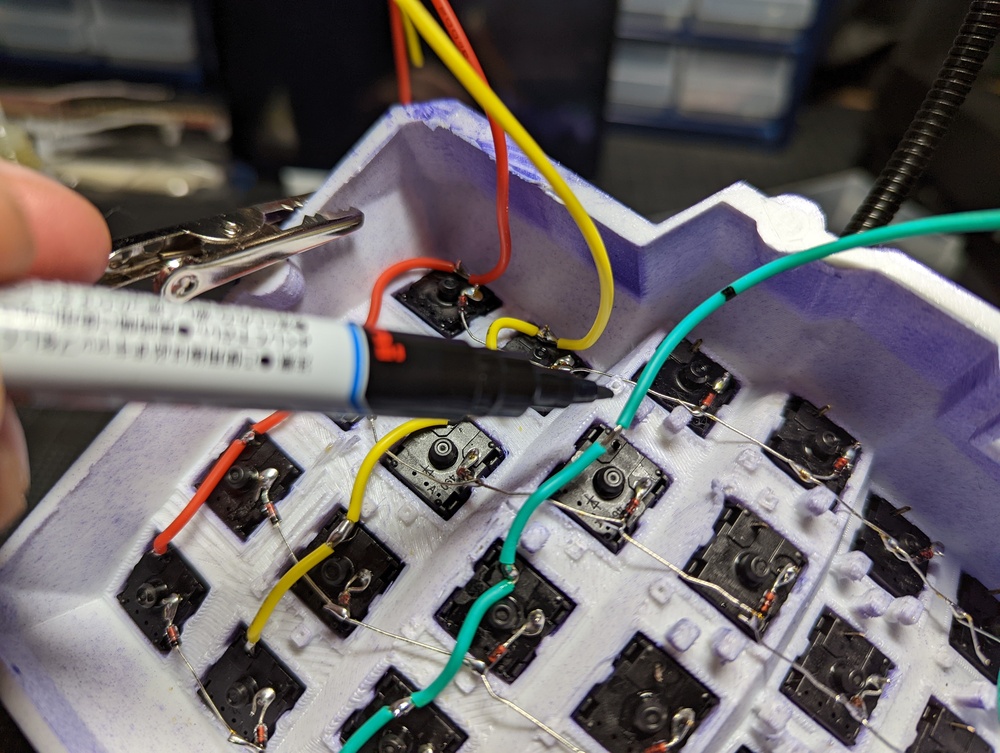
Then I use a wire stripper to remove the insulation where the wire is marked. That way we can connect the same wire to multiple keys without having to cut the wire. The exposed part of the wire can also be pushed down over the key pin to get it to stay put while being soldered into place
Soldering largely done! Having some helping “hands” is highly recommended
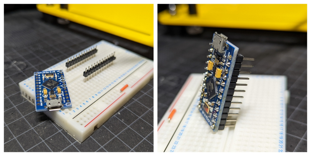
Soldering pins to the Arduino Pro Micro
To make soldering of the pins easier I simply push them into a breadboard for support
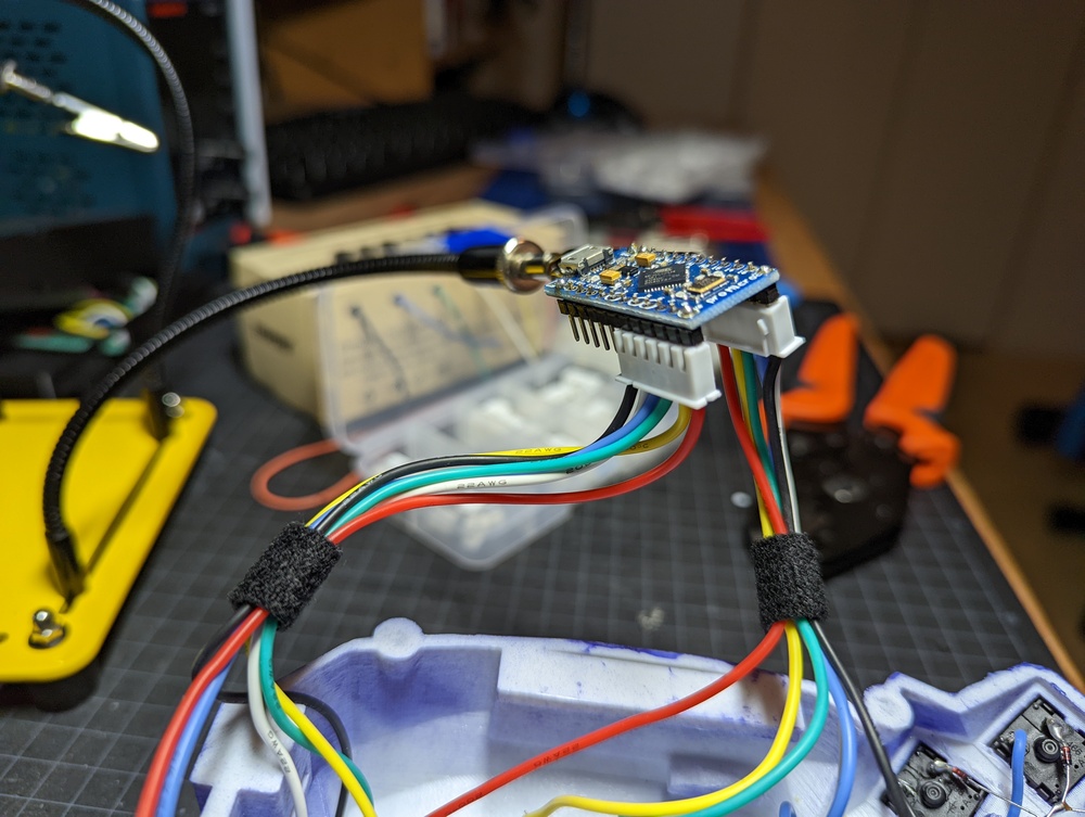
Attaching the wires to the Arduino
To avoid the hassle of soldering each Arduino pin to the keyboard wires, and also to make it easy to replace the Arduino / wires if required, I use a crimping tool and some XH connectors.

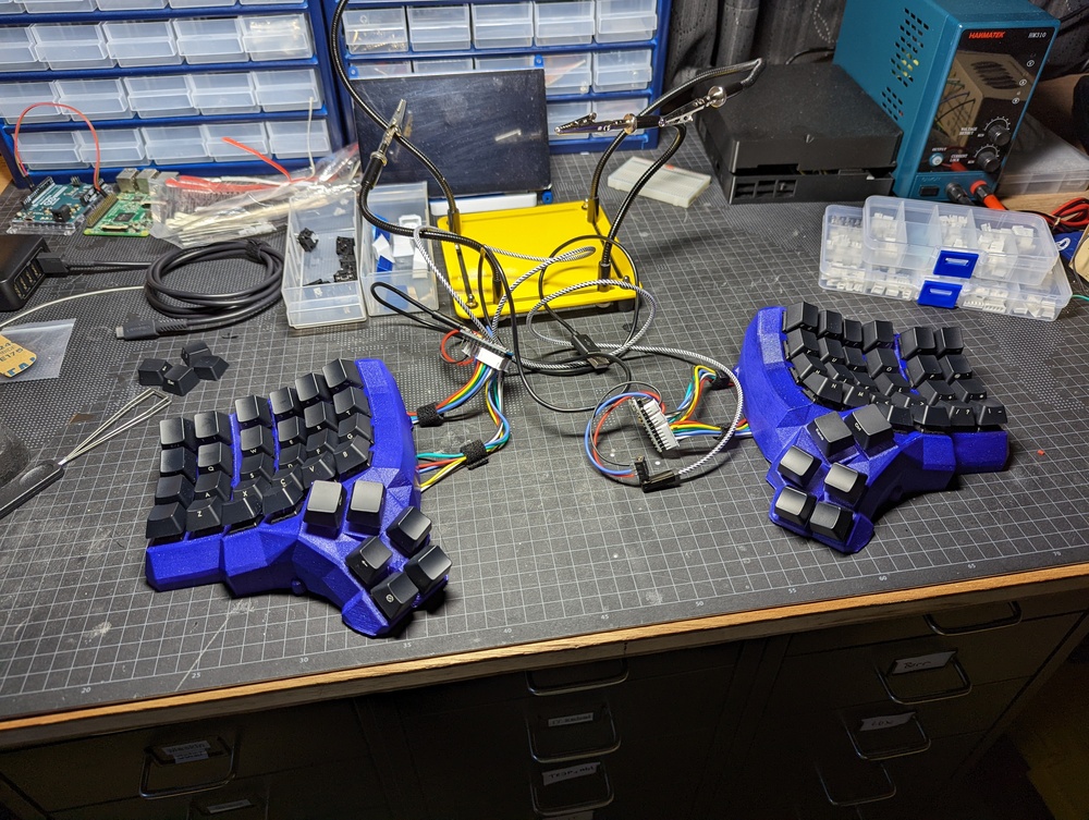
Once the wires are attached to the XH connectors they can easily be connected to the pins of the Arduino. Some velcro keeps everything nice and tidy.
Adding the 3.5mm audio jacks
I solder VCC and GND wires to the black 3.5mm audio module and attach them to the corresponding pins on the Arduino using another XH connector. The data pin attaches to D3.
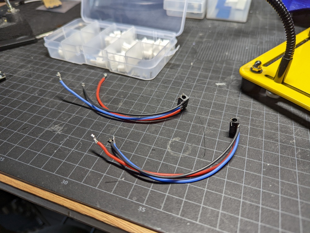
The two halves can now be connected using the 3.5mm audio cable (gray in the picture)
Programming the keyboard
QMK is used for the programming. The getting started guide can be found here: https://docs.qmk.fm/#/newbs_getting_started
The QMK firmware can be cloned from GitHub here: https://github.com/qmk/qmk_firmware
Keyboard layout: This is a handwired Dactyl Manuform 5×6, so the files for modifying the key layout and function can be found here: https://github.com/qmk/qmk_firmware/tree/master/keyboards/handwired/dactyl_manuform/5×6
Please adjust to the model of keyboard you are building if different from this.
After having created a custom layout (or if you just use one of the pre-existing ones), attach the keyboard over the micro-USB to USB-A cable to the computer and program it with:
qmk flash -kb <path-to-your-kbd-type> -km <your-kbd-layout>For example
qmk flash -kb handwired/dactyl_manuform/5x6 -km jwrQMK will compile and then flash your Arduino. When prompted, reset the Arduino by by shortcutting the RST and GND pins.
After having programmed the left side of the keyboard, just attach the other side and repeat the process.
LED lighting: Adding background lighting is likely the next thing I’ll do. There is good documentation for this here: https://github.com/samhocevar-forks/qmk-firmware/blob/master/docs/feature_rgblight.md
Conclusion
All done! Hope that was helpful and will assist with your own build!