災害発生時にはすべてのワークロードが重要で回復が必要ですが、それぞれが異なる回復時間要件を持つ場合があります。短い回復時間を必要とするアプリケーションやサービスについては、Nutanixの組み込みDRツールを使用してオンプレミスから小規模なNC2 on AWSクラスタへのレプリケーションを設定してください。
一方、少し長めのRTOで問題ないワークロードの場合、Amazon S3にレプリケートすることで運用コストを削減できます。災害時には、これらのワークロードをS3からNC2 on AWSクラスタにリカバリーします。この方法は、通常運用時に小規模かつコスト効率の高いNC2 on AWSクラスタを維持し、S3からワークロードを回復する必要がある場合にクラスタをスケールアウトする柔軟性を提供します。
ゼロコンピュートオプション
さらに、NC2 on AWSを使用したゼロコンピュートDR戦略を構成することも可能です。この場合、NC2クラスタは存在せず、オンプレミス環境がAmazon S3にデータを直接レプリケートします。ただし、このトピックは別のブログ投稿で取り上げます。
この時点でフェイルオーバー、またはテストを行い、レプリケートされたデータからの復旧が可能であることを確認できます。これを行う際、S3のデータからフェイルオーバーするため、VMを復旧するターゲットクラスタを選択する必要があります。「+ Add Target Clusters」をクリックし、以下のようにNC2 on AWSクラスタを選択します:
警告が表示され、S3から復元されるVMの流入を処理するためにNC2 on AWSクラスタに追加ノードを必要とする場合があることを強調されます。必要に応じて、NC2管理コンソールを使用してノードを追加することでクラスタを拡張します。
フェイルオーバー後、VMがNC2 on AWSで問題なく稼働していることを確認できます。
まとめ
この記事では、NC2 on AWSのPilot Lightクラスタを使用した災害復旧の設定方法についてガイドとデモンストレーションを行いました。詳細については、以下のドキュメントリンクを参照してください。この内容が分かりやすかったことを願っています。具体的な使用事例や環境についてさらに情報が必要な場合は、お近くのNutanix担当者にお問い合わせください。
This guide covers NC2 concepts and demonstrates how to configure an Azure network environment for deploying Nutanix Cloud Clusters (NC2) on Azure. While NC2 can be deployed quickly and easily through the NC2 portal inclusive of the creation of required VNets, subnets, and other Azure resources—this method may impose limitations on post-deployment modifications.
For instance, if the VNets are created via the NC2 portal, it may not be possible to transition a non-redundant configuration into a redundant or scale-out configuration. To address this, this guide provides step-by-step instructions for manually creating the necessary Azure network resources. Additionally, it highlights key considerations to ensure a smooth and successful deployment process.
Single vs. Scale-out Flow Gateway (FGW)
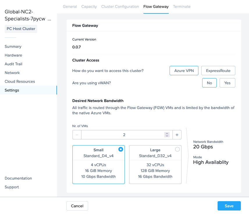
North-South traffic flow for workloads / User VMs (UVMs) on NC2 on Azure goes via one or several Flow Gateway (FGW) VMs. Since all outbound UVM traffic goes through these VMs, please select the number required based on the throughput you need for the workloads on your NC2 cluster. There are two types of FGW which support 10Gbps and 16Gbps of throughput each respectively.
These FGW VMs are not deployed on NC2 on Azure. Instead they are deployed as Azure native VM instances. Each FGW connects to an External and Internal Azure subnet. The NC2 cluster is set to send all external-facing traffic over Equal-cost Multipath (ECMP) with these FGW VMs as the next hop.
These FGW’s can be deployed in single or scale-out mode. As would be expected, single implies the FGW is a single point of failure. However, the health of the FGW is continuously monitored by the NC2 portal and it will be re-provisioned in case it malfunctions.
For scale-out, or redundant mode, two, three or a max of four FGW VMs are deployed in an active/active formation where traffic can flow through any and all of the VMs.
The above screenshot is from the NC2 portal where from the “Settings” menu we have highlighted the “Flow Gateway” tab to allow us to view and update FGW and other network related settings.
BGP speaker VMs
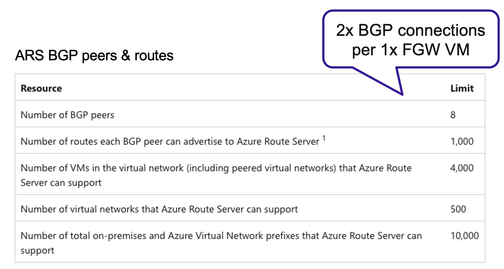
When scale-out FGW is selected, routing shifts from using static routes (UDR) to Border Gateway Protocol (BGP). Two BGP VMs will be automatically deployed if the FGW configuration changes from single to scale-out and those BGP VMs will need an Azure Route Server (ARS) to talk to.
Each FGW uses two BGP sessions on the ARS which the BGP VMs are paired with. Since the soft BGP session limit for ARS is 8, please ensure your ARS have sufficient sessions available when scaling out your FGW configuration.
Azure quotas
Prior to deploying it is good practice to verify that Azure subscription isn’t running out of the type of resources which will be required for the NC2 on Azure deployment. This includes the ARS BGP sessions mentioned in the section above as well as the FGW VM types, vCPU, memory and storage.
The small FGW VMs are of type Standard_D4v_4, the large FGW VMs are Standard_D32_v4 and the two BGP VMs are of type “Standard_D4_v4 type” (4 vCPUs and 16 GiB mem).
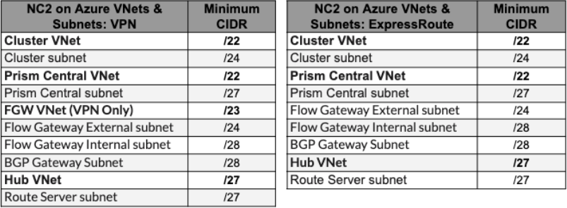
The bare minimum amount of VNet’s required to deploy NC2 on Azure is two, but you likely need more. For example, having a Hub VNet for routing traffic between on-prem and Azure as well as between VNet’s. We will look at two configurations in this post: ExpressRoute and S2S VPN. Note that all VNet’s need to be peered in a mesh fashion.
The VNet’s which are always required are the Cluster VNet for the bare metal cluster nodes on which NC2 is deployed as well as the Prism Central VNet which is used by the Prism Central management VM(s).
Both the bare-metal cluster nodes and the Prism Central management VM(s) require subnets delegated to the MS bare.metal service to function. Azure restricts the number of bare.metal subnets in a VNet to one. That forces us to create two VNet’s with a bare.metal delegated subnet each.
The FGW VMs need two subnets: One Internal for connecting to the NC2 network controller and one External for connecting to the outside world. Additionally, the BGP speaker VMs need a subnet for themselves too. That brings the number of subnets up to three. In an ExpressRoute environment these subnets can be co-hosted in the Prism Central VNet. However, in a S2S VPN environment we need to create a third VNet to host these resources. Let’s refer to the third VNet as the FGW VNet.
Please see the below CIDR ranges as guidance only. Always refer to the official documentation for the latest updates.
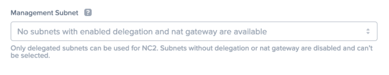
The NC2 portal will complain if required subnets aren’t available for deployment. In this example the VNet lacks a subnet delegated to the bare.metal service.
NAT Gateways
The NC2 cluster, FGW VMs and other resources need to be able to communicate with the NC2 portal as well as various other endpoints outside the NC2 environment. These are detailed in the prerequisites part of the user guide. NAT Gateways are required to provide that internet-facing access and the NC2 portal will check that these are present during deployment. Deploying NC2 without NAT Gateways is possible but necessitates reaching out to Nutanix support to disable the NC2 portal check prior to deploying. In that case internet access would need to be provided through a Network Virtual Appliance (NVA) and vWAN. Please refer to the NC2 on Azure networking best practices guide for more detail.
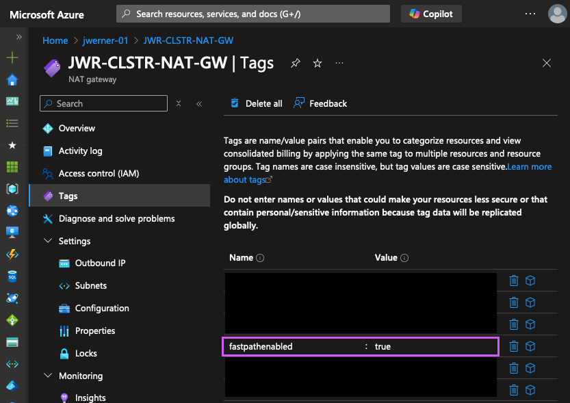
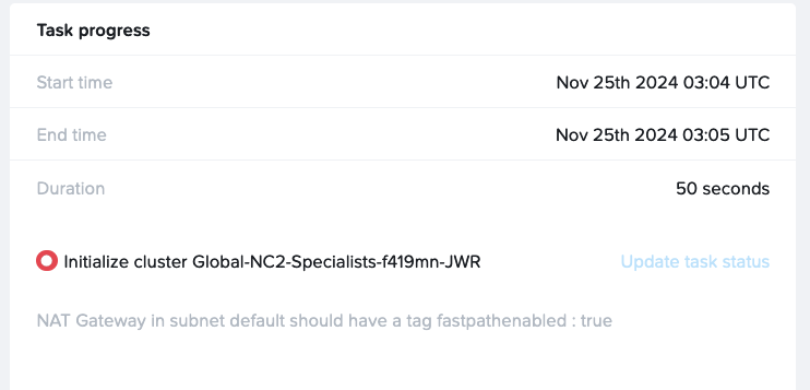
“fastpathenabled”: Note that at the time of writing (December 19th 2024) the NC2 portal requires every NAT Gateway used with NC2 to have the “fastpathenabled” tag set to “true” for deployment to proceed. The tag can be added to existing NAT Gateways and doesn’t have to be present at time of NAT GW creation.
Below is an example of an error where one of the NAT Gateways used doesn’t have this tag configured.
Custom DNS server settings
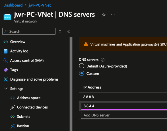
Prior to deploying, please update the DNS server settings on each VNet to be used with NC2 to replace the Default (Azure-provided) DNS with a custom DNS server. In this example we use the Google 8.8.8.8 and 8.8.4.4 servers, but other DNS resolvers can be used too, including private DNS servers – provided they can also resolve all required public endpoints. Note that deployments to VNets with the Default DNS server configured will fail.
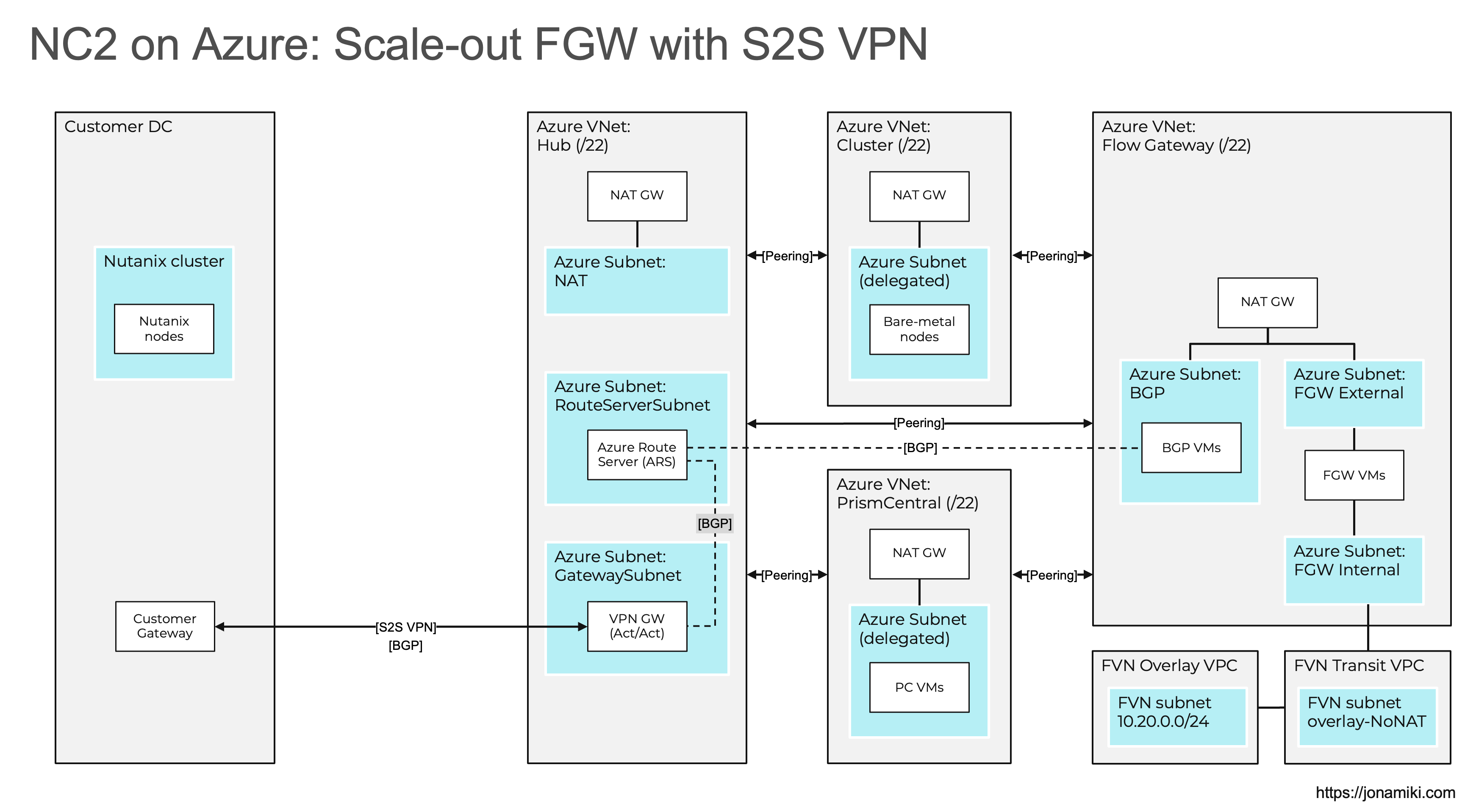
Solution architecture diagrams
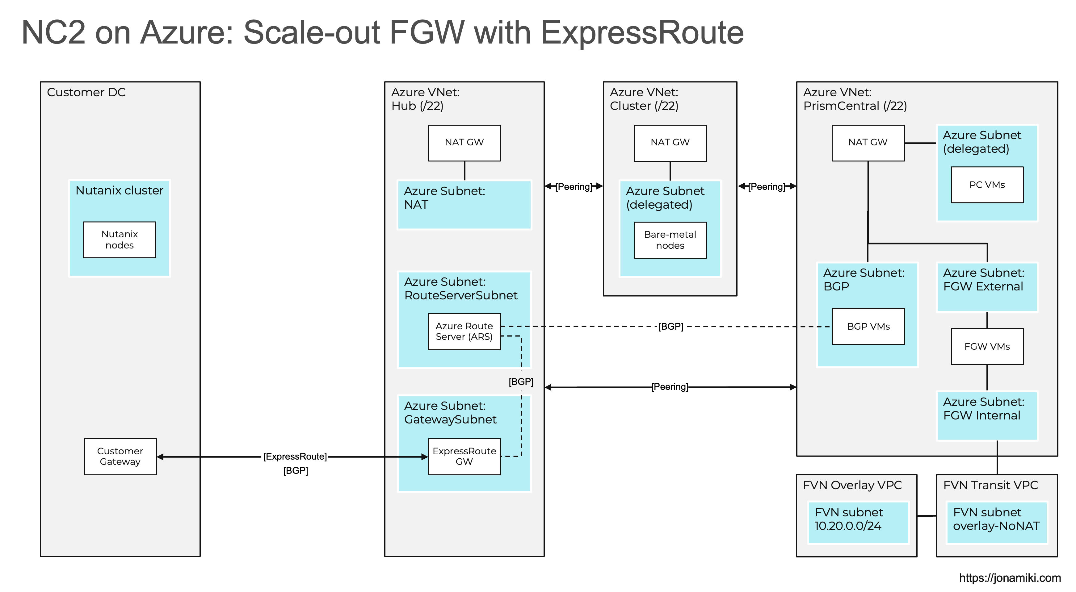
The Azure VNets are prefixed with “Azure” and on the bottom right there are two Flow Virtual Networking (FVN) VPCs prefixed with “FVN”. The FVN components are all created on top of the NC2 cluster and aren’t directly visible in the Azure management console. There are many more ways of configuring NC2 on Azure, but those are out of scope for this blog post. Please refer to the documentation for more detail.
ExpressRoute
As discussed above, the ExpressRoute option we have the benefit of co-hosting the FGW and BGP subnets in the Prism Central VNet.
Site-to-Site VPN
For the S2S VPN option we add the FGW VNet which will be used to host the FGW internal, external and the BGP subnets.
VNet peerings
When peering your VNets, please ensure to do a full mesh, as is show in the diagrams. In other words – Every VNet need to be peered with every other VNet.
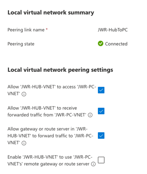
When peering from the Hub VNet, please use the following settings:
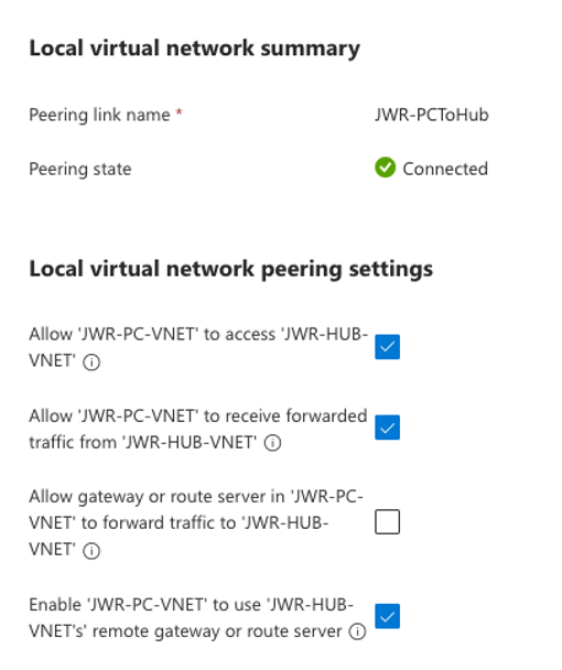
When peering from one of the other VNets (Cluster, Prism Central, FGW) to the Hub VNet, please use the following settings:
Summary and conclusion
In this blog post, we explored the foundational concepts of NC2 on Azure networking and presented solution architectures for two key use cases: ExpressRoute and Site-to-Site (S2S) VPN. We highlighted the required configurations, potential challenges, and important considerations.
By combining this guide with the official documentation, we aim to provide a clear path for manually creating Azure network infrastructure in preparation for an NC2 deployment.
We hope you found this information helpful. In our next post, we will dive deeper into the BGP component and demonstrate how to route traffic for overlay no-NAT networks. Stay tuned!
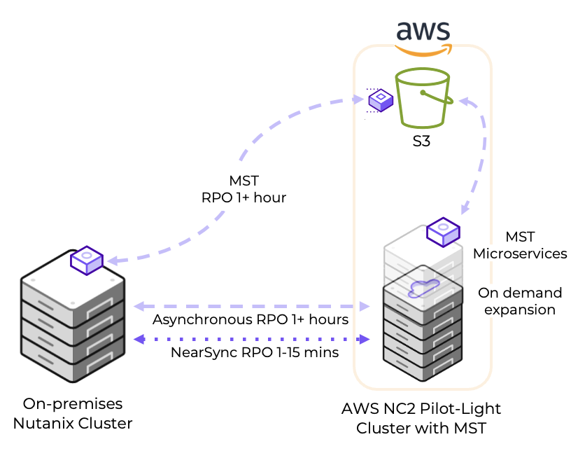
Configuring a Disaster Recovery (DR) from on-premises to Nutanix Cloud Clusters (NC2) on AWS is straight-forward and can provide significant benefits for those responsible for ensuring Business Continuity. With a Pilot Light cluster this can even be done for workloads with two different levels of Recovery Time Objective (RTO) while saving on costs by minimizing NC2 cluster size during normal operations.
Workloads can all be important and vital to recover in case disaster strikes, but may have different requirements when it comes to how quickly they must be back online again. For applications and services with short recovery time windows, simply configure replication from on-premises to a small NC2 on AWS cluster using the Nutanix built-in DR tools.
For workloads which are fine with a slightly longer RTO, save on running costs by replicating them to Amazon S3. In case of disaster those workloads can be recovered from S3 to the NC2 on AWS cluster. This brings benefits in the ability to keep the NC2 on AWS cluster at a small and cost-efficient size during normal conditions, with the ability to scale out the cluster if there is need to recover workloads from S3.
Zero-compute option
There is additionally possible to configure a Zero-compute DR strategy with NC2 on AWS in which there is no NC2 cluster and the on-premises environment replicate data directly into Amazon S3, however that will be covered in a separate blog post.
Zero-compute DR offers even lower costs than Pilot Light since there is no need to deploy an NC2 cluster unless there is a disaster. However, it will increase RTO because the NC2 infrastructure need to be provisioned. Therefore, Zero-compute is cheaper from a running-costs perspective, but may incur higher costs to the business during a DR event due to the longer time required to deploy and configure the recovery cluster.
Solution architecture
The below diagram shows how it is possible to replicate both to Amazon S3 as well as to the NC2 on AWS cluster. Both with different RPO times.
Versions used
For this deployment we use the following versions:
Entity
Version
NC2 on AWS Prism Central
pc.2024.3
NC2 on AWS AOS
7.0
On-premises Prism Central
pc.2024.2
On-premises AOS
6.8.1 (CE 2.1)
Deployment steps
Configuring a Pilot Light cluster can be done in just a few hours. For the purpose of this blog post we have gone through the following steps:
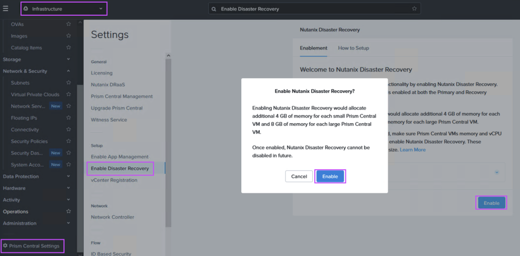
Step 1: Deploy an NC2 on AWS cluster and enable DR
This can be done with a few clicks in the NC2 portal. Either deploy into an existing AWS VPC or create new resources during cluster deployment. If an existing VPC with connectivity to on-prem is used it will make setting things up even faster since routing is already configured.
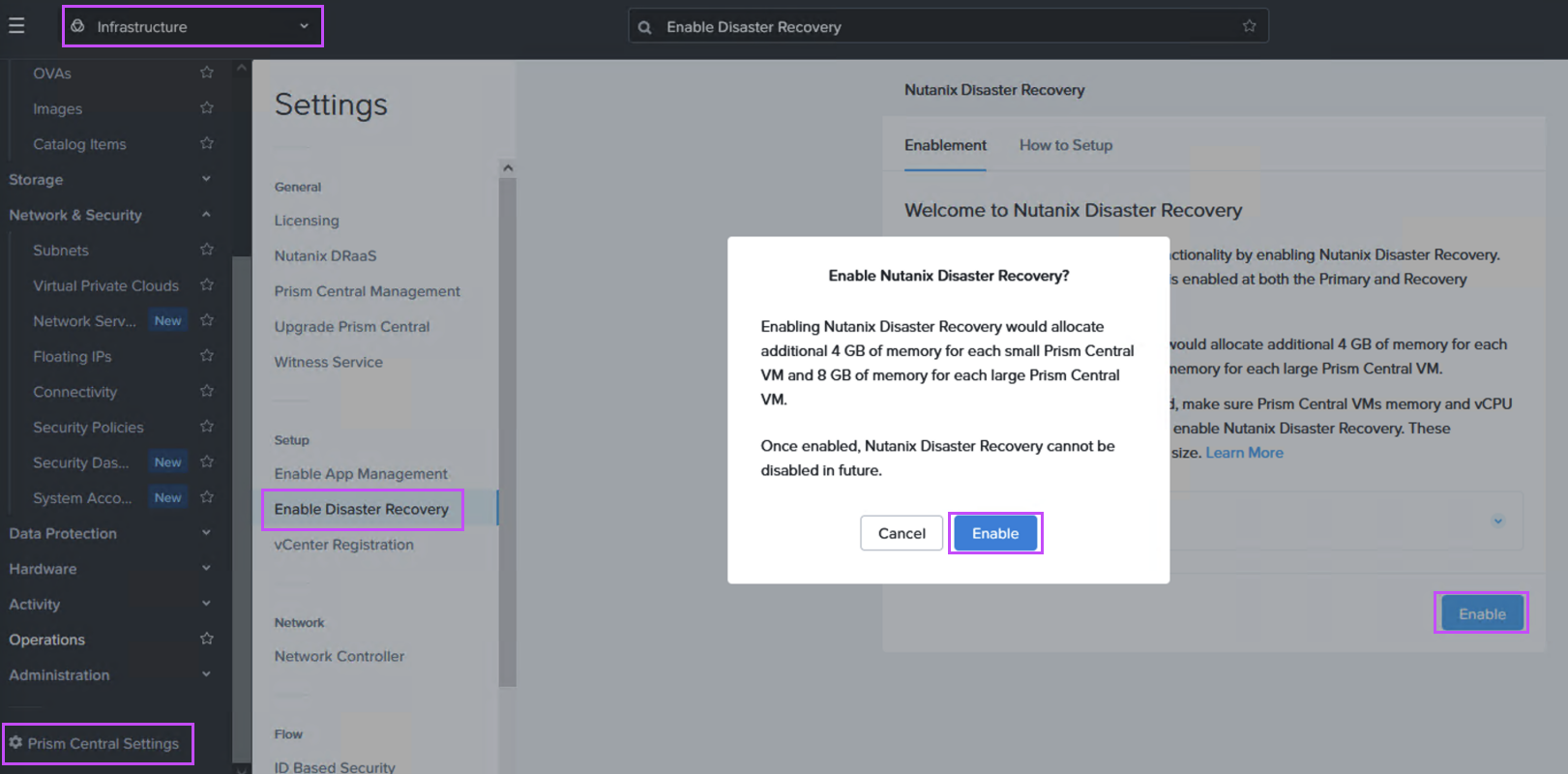
Navigate to the Prism Central settings menu and enable Disaster Recovery as shown:
Step 2: Add connectivity between on-prem and AWS (if not already configured)
Configure Direct Connect or a S2S VPN to link the on-premises Nutanix cluster environment with the AWS VPC holding NC2 on AWS.
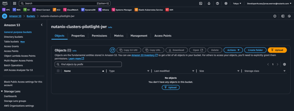
Step 3: Create an S3 bucket to store replicated data
Create an S3 bucket which can be accessed from the NC2 on AWS environment. Make sure to give it a name starting with “nutanix-clusters”. You can add on something in addition to keep buckets separate. In this example we use “nutanix-clusters-pilotlight-jwr” as the bucket name.
If not already created, create a user with full access to this bucket and make note of the Access and Secret Access keys as they are used in the next step. An example of a policy which gives full access to our bucket can be found below:
Step 4: Configure MST on Prism Central in NC2 on AWS
MST will deploy a number of Virtual Machines and this deployment requires us to provide three IP addresses on the AWS native VPC CIDR range.
If NC2 was deployed with AWS native networking, simply provide IP addresses outside of the DHCP range on one of the existing networks, or alternatively add a new AWS native subnet through the Prism Central console.
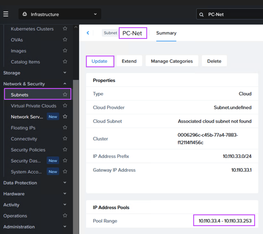
If NC2 was deployed with Prism Central and Flow Virtual Networking (FVN), the easiest way to do this is to shrink the automatically created “PC-Net” DHCP range to make some space for MST. We shrink ours from ending at “10.110.33.253” to end at “10.110.33.200”. Make sure the no VMs are using addresses in the space you are creating.
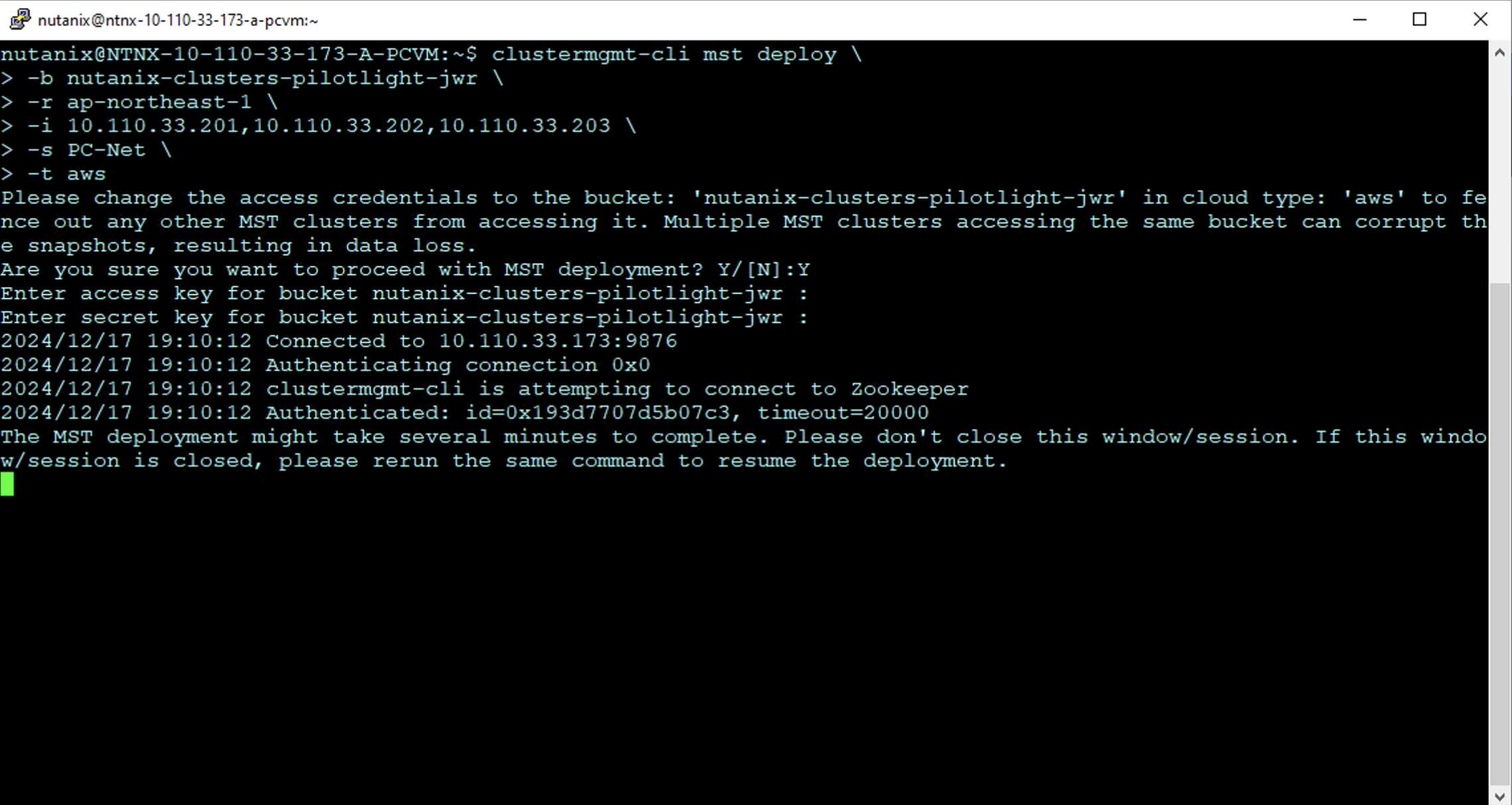
SSH or open a console window to Prism Central using the “nutanix” user and enter the below command to start the deployment:
The MST deployment begins as shown. Enter the AWS access key and secret access key for the user with rights to the S3 bucket when prompted.
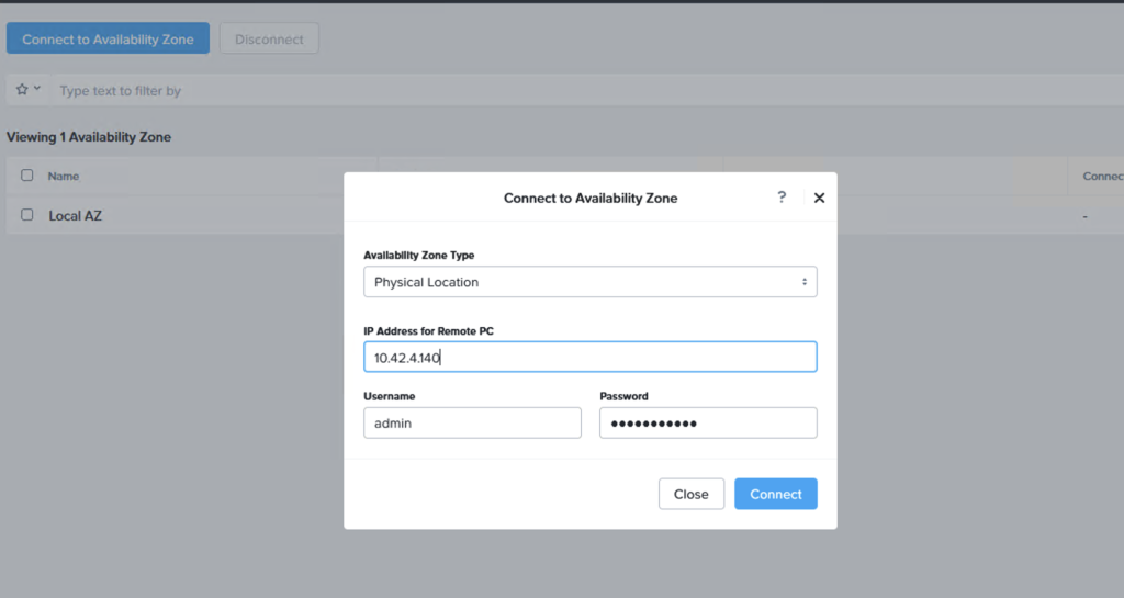
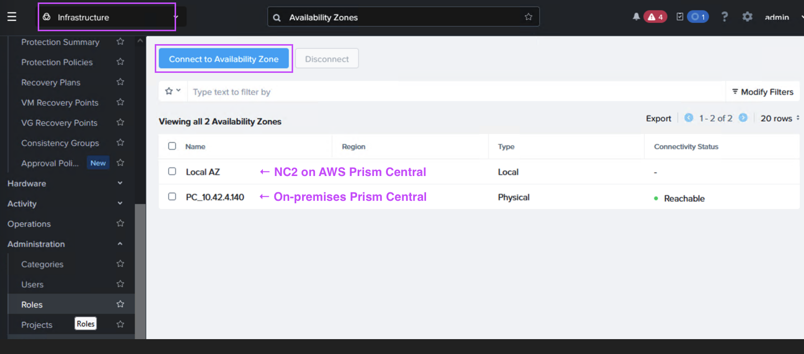
Step 5: Link the on-premises Prism Central with the NC2 Prism Central
In Prism Central (on-premises or NC2), navigate to “Administration” and “Availability Zones” and add the other Prism Central instance as a remote physical site.
Step 6: Create a Protection Policy and DR Plan
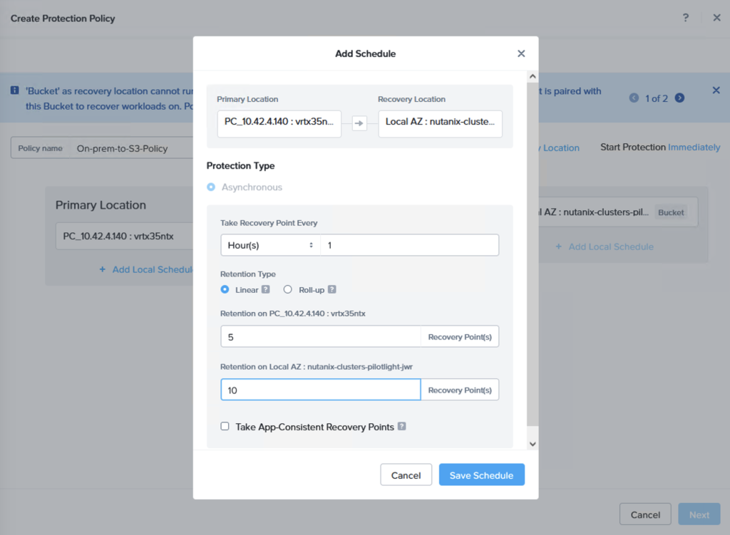
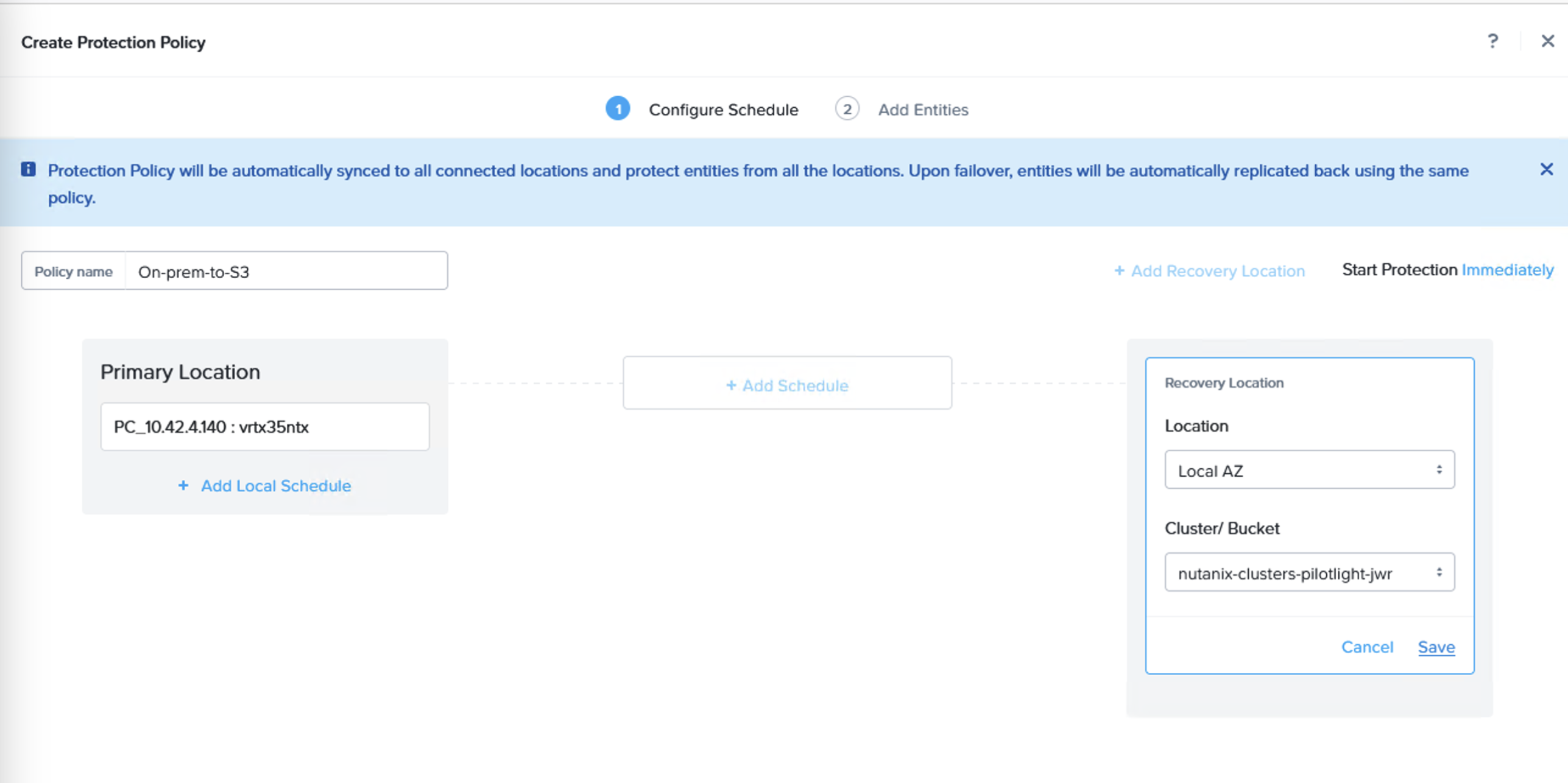
Through the Prism Central console, navigate to Data Protection and Protection Policies. From here, create a new Protection Policy with the on-premises cluster as source and the Amazon S3 bucket as target.
A replication schedule can be set and allows Linear snapshots for maximum of 36 snapshots or Roll-up where data can be retained for up to one month.
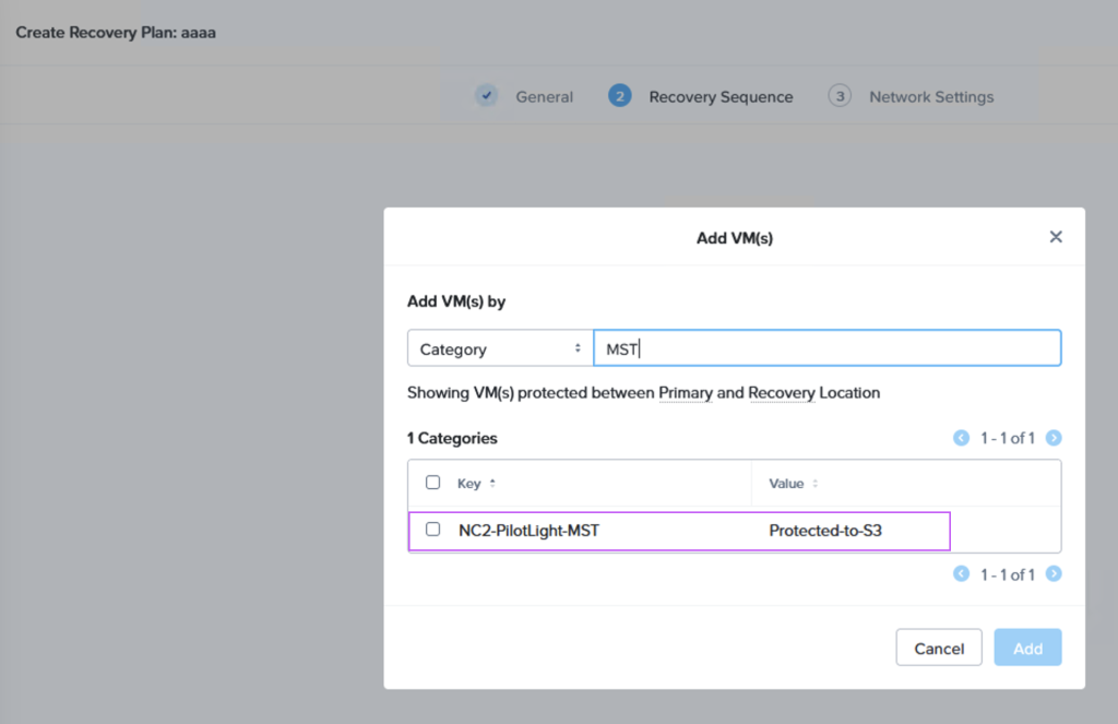
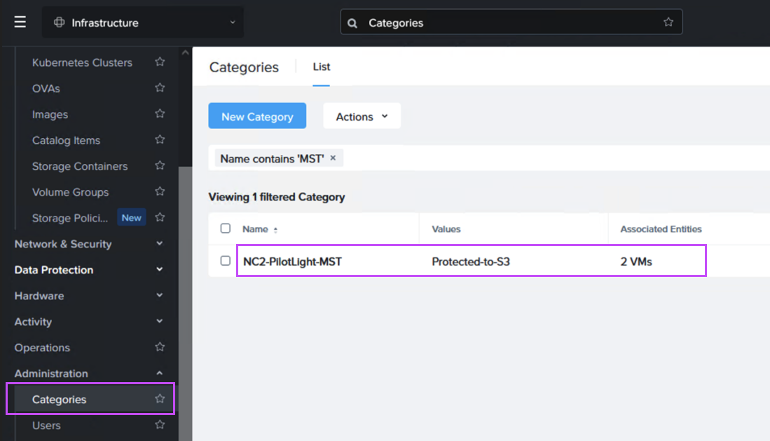
Next we create a Recovery Plan. Optionally, to facilitate grouping of those VMs which are destined for Amazon S3 and those destined to be replicated directly to the NC2 cluster, we create two categories to place them in. Below is the category for the VM group which is to be replicated to S3.
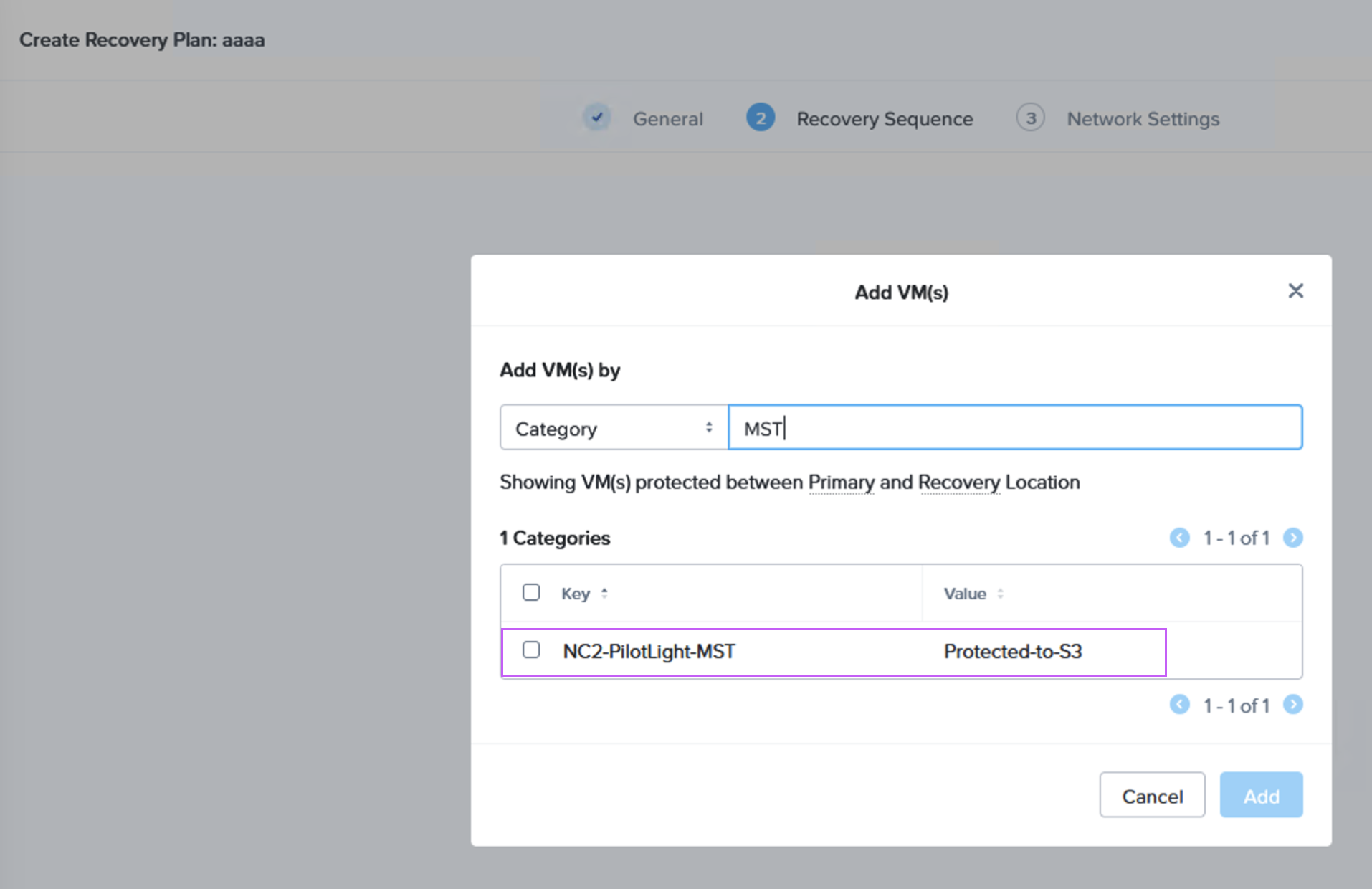
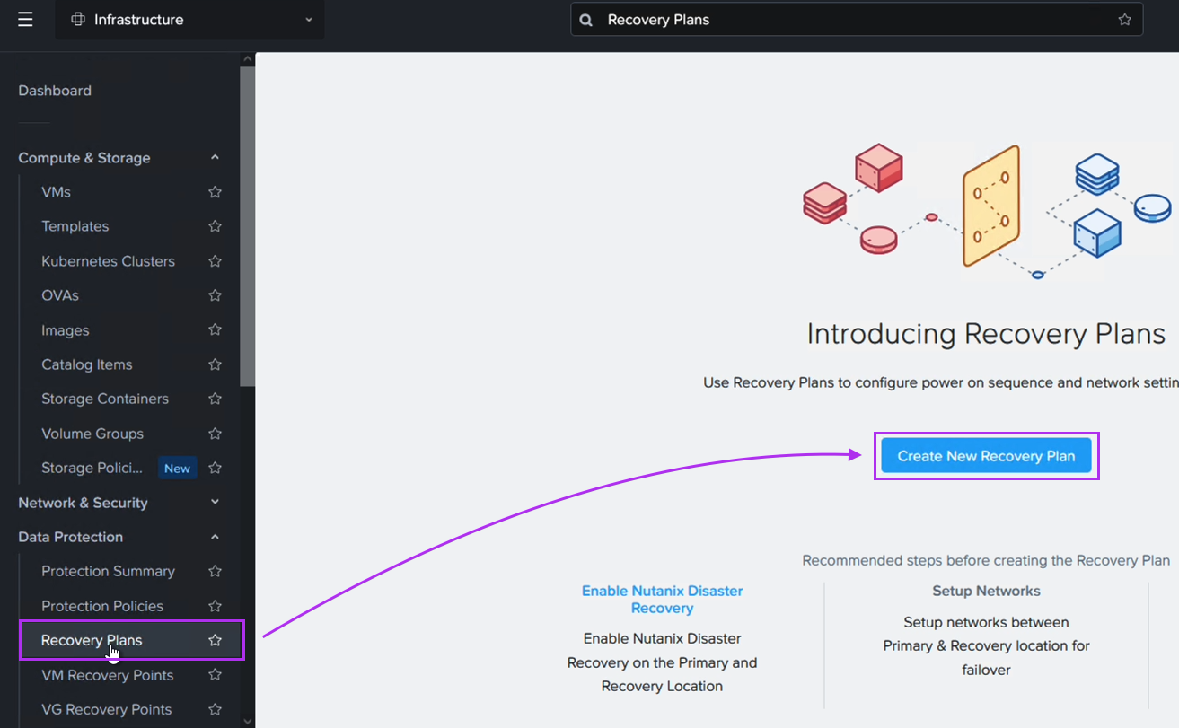
When we then go to Data Protection and Recovery Plans we reference our category to get the correct VMs replicated to the correct location, as follows:
Verifying that data is replicated to S3 + Failing over
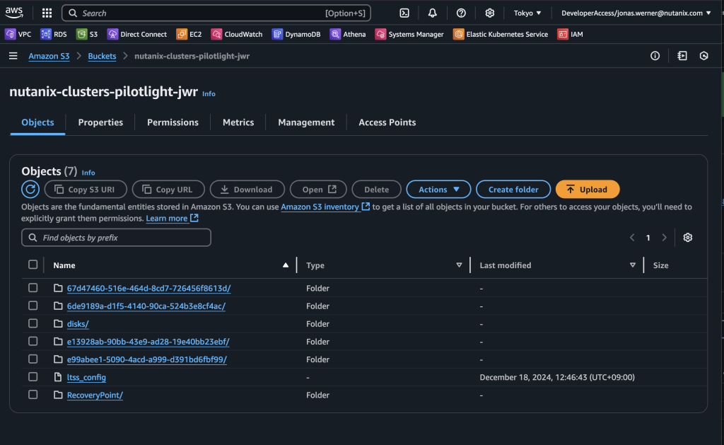
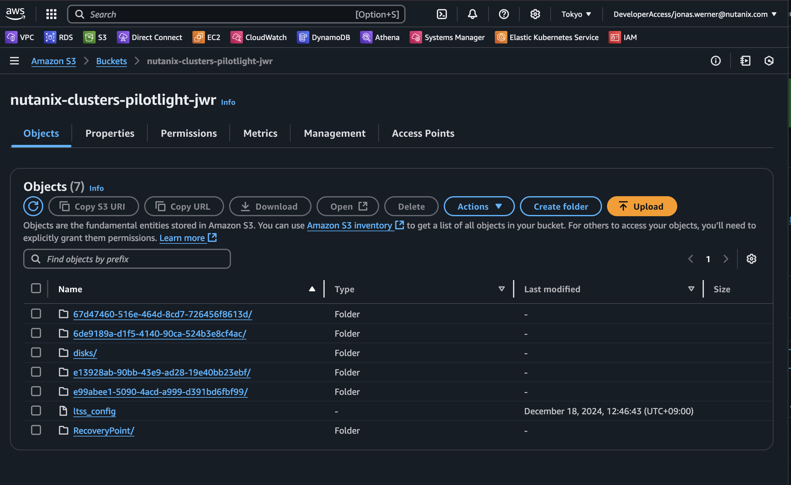
Now the replication schedule is set and the target VMs are highlighted through categories to ensure they are replicated. By checking our S3 bucket we can verify that snapshots have been sent to S3 from the on-premises cluster.
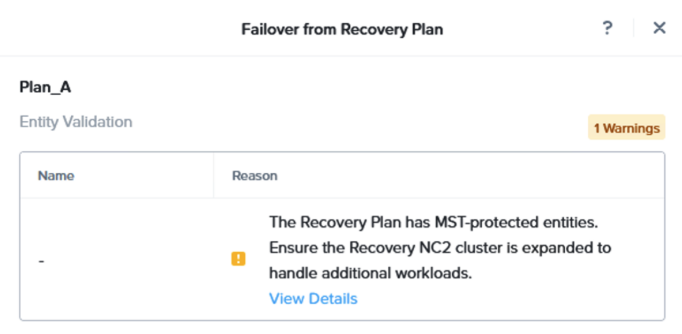
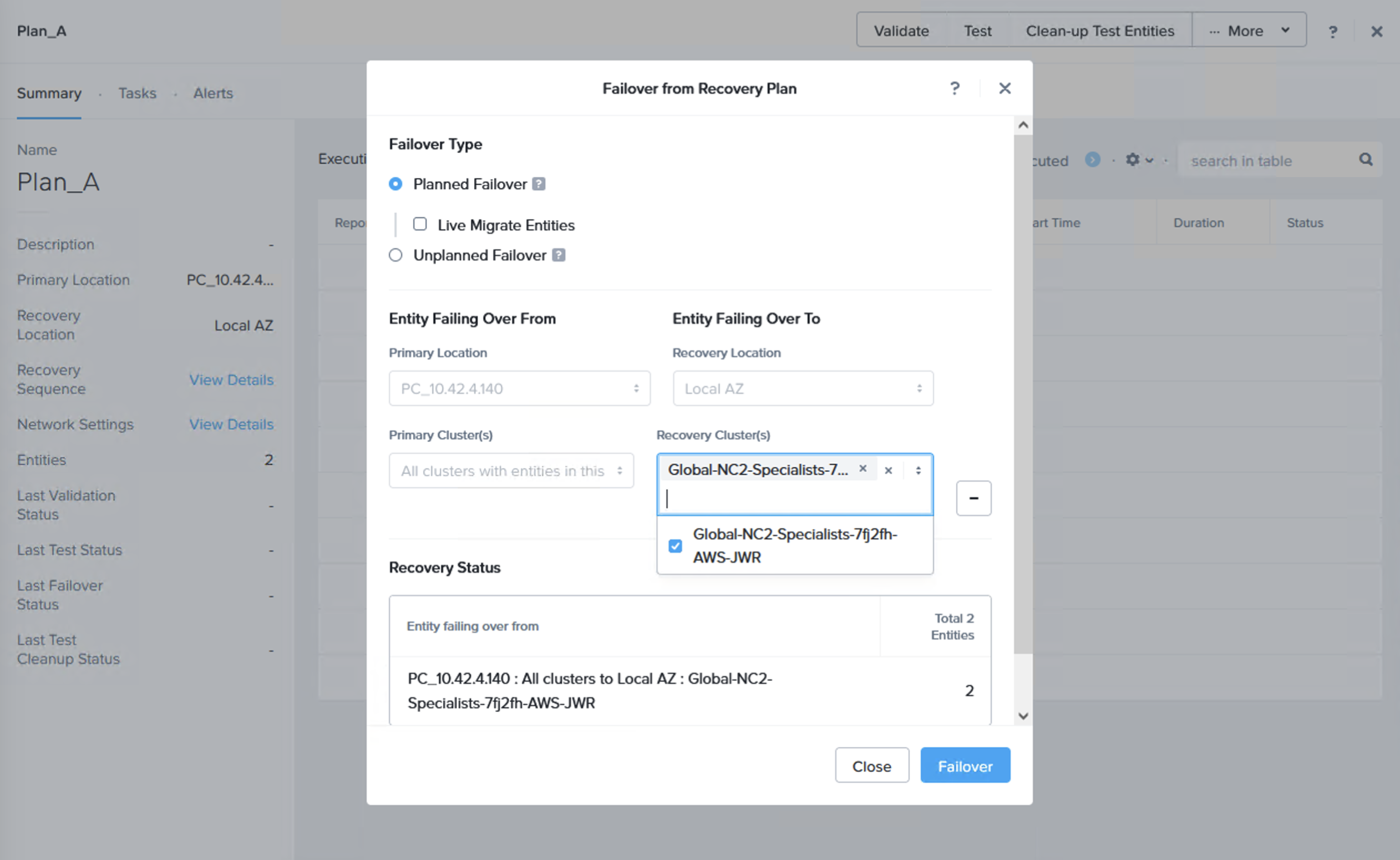
We can now do a failover or just a test to see that it is possible to recover from the replicated data. When you do this, since we are failing over from data in S3, make sure to select the target cluster to which we want to recover the VMs. This is done by clicking “+ Add Target Clusters” and selecting the NC2 on AWS cluster as per the below:
You will get a warning highlighting that there may be a need to expand the NC2 on AWS cluster with extra nodes to handle the influx of VMs being restored from S3. If required, simply expand the cluster by adding nodes through the NC2 management console.
After failing over we can verify that our VMs are up and running in NC2 on AWS without issues.
Wrap-up
This has been a guide and demonstration of how easy it is to configure Disaster Recovery using a Pilot Light cluster with NC2 on AWS. Please refer to the links below for more detail in the documentation. Hopefully this has been easy to follow. Please feel free to reach out to your nearest Nutanix representative for more information and guidance for your specific use case and environment.
移行後 DynamoDBに保存した情報をテンプレートとして使用するPythonスクリプトを実行します。このスクリプトは、Nutanix Prism Central APIに接続し、既存のネットワークインターフェイスを削除し、正しい(元の)IPアドレスを持つ新しいインターフェイスを各インスタンスに追加します。
最初に、EC2インスタンスに関する情報を収集し、その情報をDynamoDBに保存します。効率を重視して、SSM Run Commandを使用してPowerShellスクリプトを実行します。これにより、WindowsおよびLinuxワークロードの両方を1回または2回の操作で簡単に処理できます。この例では、単一のWindows Server 2019 EC2インスタンスをテスト対象として使用します。
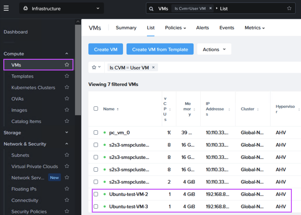
次に、Pythonスクリプトを実行して、DynamoDBに保存されたインスタンス名を参照し、それをNC2のVM名と照合します。その後、Prism Central APIを使用して既存のネットワークインターフェイスを削除し、新しいネットワークインターフェイスを追加します。この新しいインターフェイスには、元の静的IPアドレスが設定されます。
Some customers require cross-region disaster recovery (DR) in AWS but often face the challenge of changing IP addresses during a failover to another region. This change can disrupt external access to services running on instances covered by the DR policy.
Nutanix Cloud Clusters (NC2) address this challenge with built-in DR functionality that ensures IP addresses remain consistent during failovers between regions. Bonus: It is possible to over-provision CPU on NC2, so it may actually be possible to save on compute costs after the migration to NC2. However it can only retain IP addresses during DR for workloads which are already residing on a Nutanix cluster, so we have to migrate the EC2 instances first.
The free Nutanix Move migration tool can migrate workloads from Amazon EC2 to Nutanix Cloud Clusters, though it currently lacks support for IP retention. In this blog we use some creative workarounds to maintain consistent IPs throughout the migration, although note that MAC addresses will change. NC2 then retains the IPs during regional failovers as part of the Nutanix DR solution. Let’s dive in!
Software versions used during testing
AOS
6.10
Prism Central
pc.2024.2
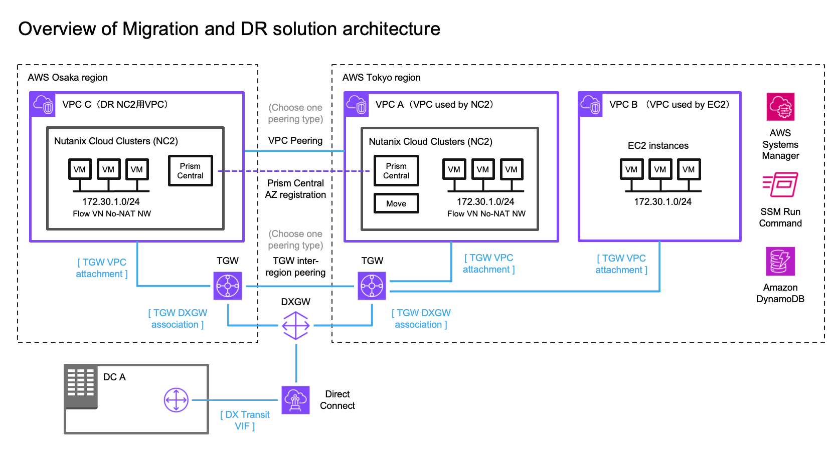
Solution architecture
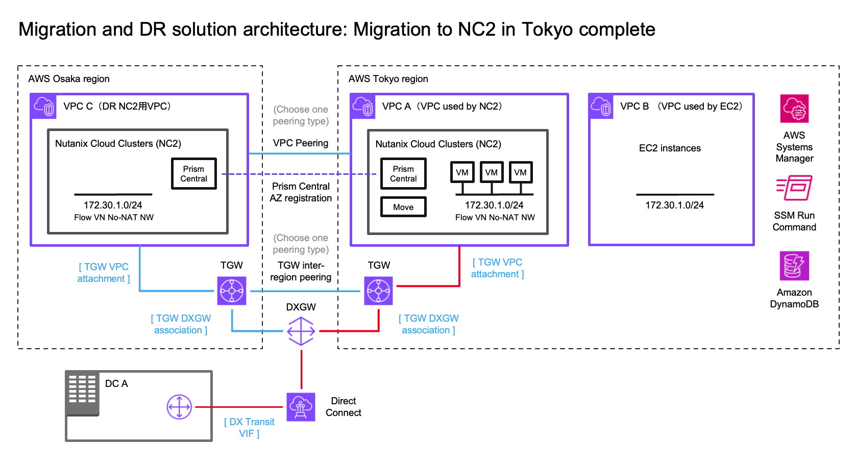
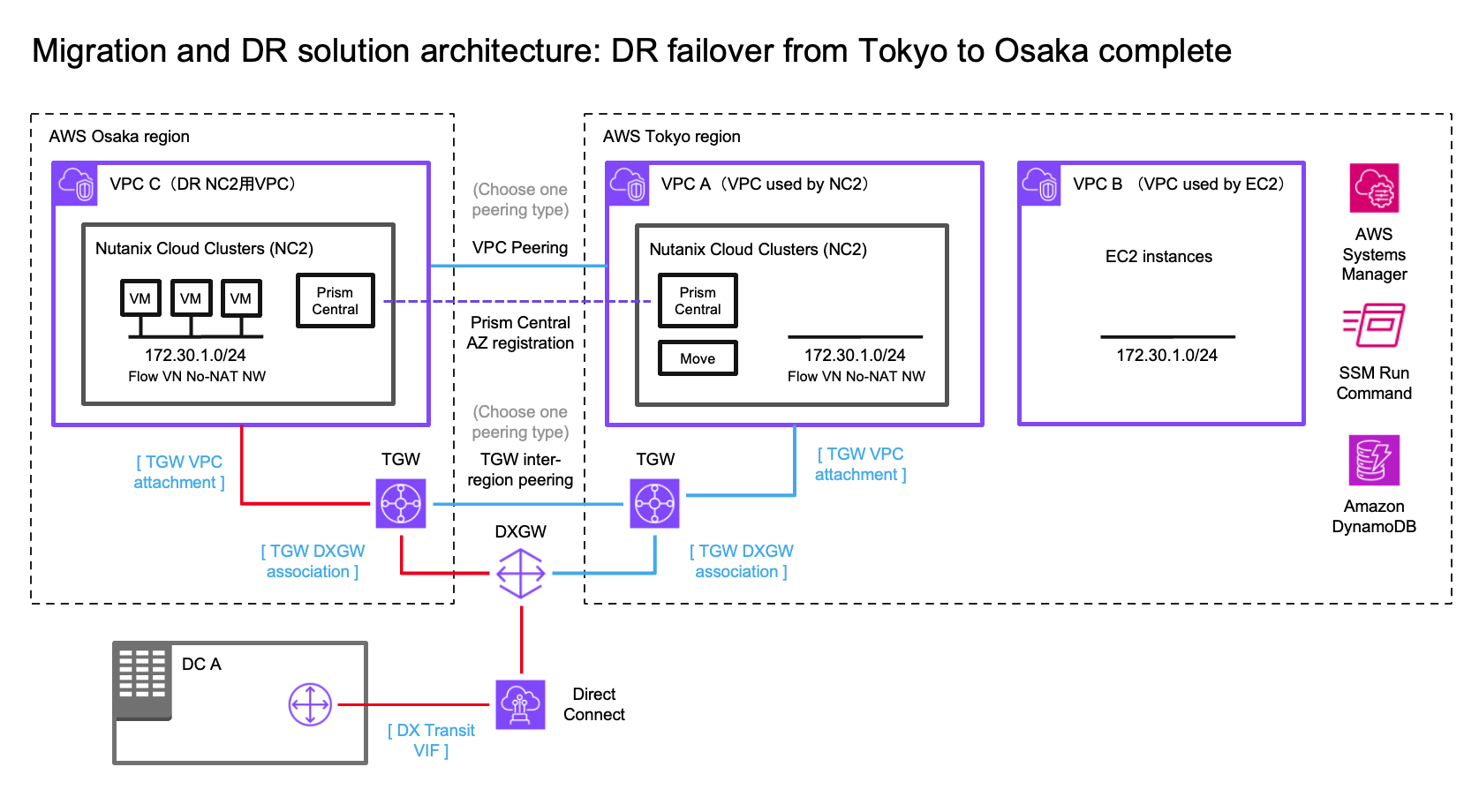
In this case we have an on-premises datacenter (DC), an AWS VPC with EC2 instances which we want to have covered by a DR policy (so they can fail over to another region without changing IP addresses) and finally two NC2 clusters – one in the primary region and one in a separate region for DR purposes. We use Tokyo (ap-northeast-1) as the primary AWS region and Osaka (ap-northeast-3) as the disaster recovery location in this example.
Overview of solution architecture. Click to embiggen.
We illustrate connectivity to the on-premises environment by using Direct Connect. Note that all the testing of this solution has been done with S2S VPN attached to the TGW’s in each region. Peering between the two DR locations can be done by using cross-region VPC peering or peering of two Transit Gateways (TGW).
Networking
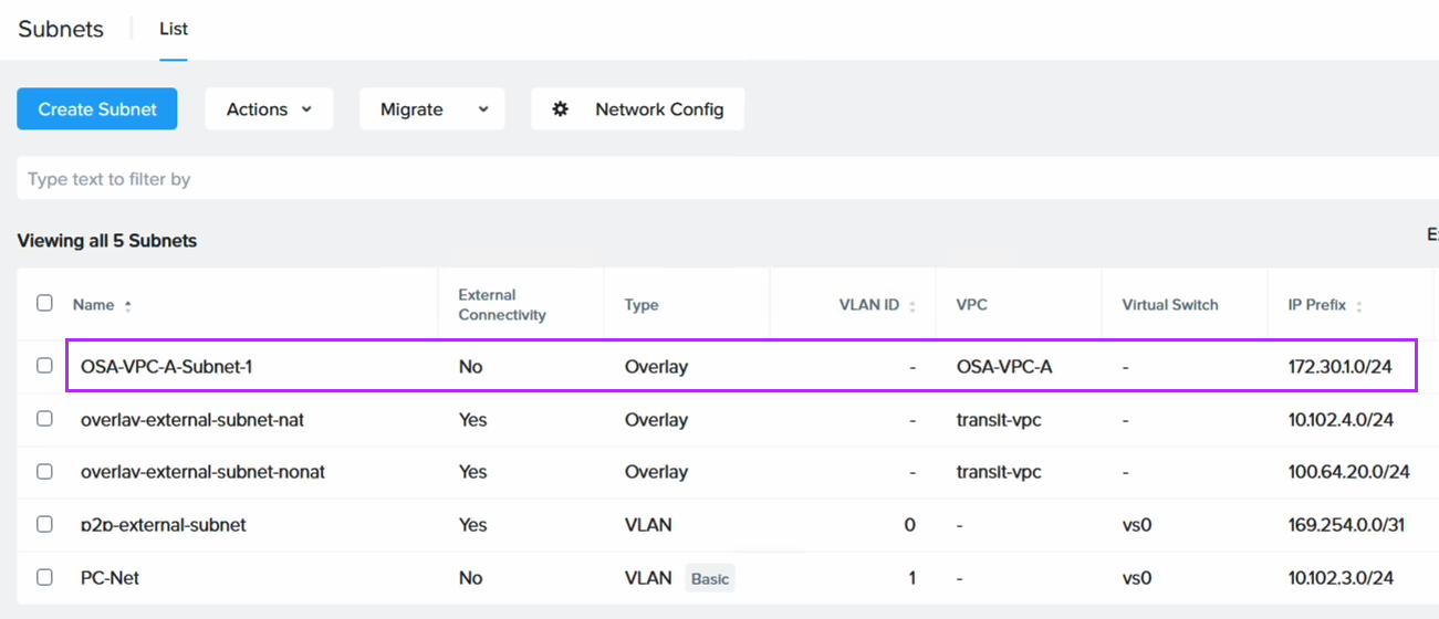
To retain the IP addresses of the migrated EC2 instances we use Flow Virtual Networking (FVN) to create overlay no-NAT overlay networks on NC2 with a CIDR range which matches that of the original subnet the EC2 instances are connected to. We create this overlay network in both Tokyo and Osaka NC2 clusters so that we can later fail over the VMs and have them attach to a network with the same CIDR range.
To ensure the on-premises DC is able to access the VMs we modify the route tables throughout the process. That way we maintain routes which point to the migrated EC2 instances, regardless of where they are located.
Automating the VPC and TGW creation with Terraform / Open Tofu
In the case you’d like to try this out yourself, the Terraform / Open Tofu templates for deploying the VPC’s, TGW’s and the routing for these can be found on GitHub here:
When to use which peering type for inter-region connectivity
Generally it can be said that VPC Peering is better for lower traffic scenarios or when the simplicity of direct peering is desirable, despite slightly higher data transfer costs incurred for VPC peering.
TGW Peering is more cost-efficient for high-traffic environments or complex architectures, where the centralized management and lower data transfer rates outweigh the additional costs per TGW attachment. Note that although traffic passes through two TGW’s, the peering interface doesn’t incur data transfer charges so the data is only charged once (roughly 0.02 cents / GiB in the Tokyo region).
The workaround for IP retention
As mentioned in the introduction, while the Nutanix Move virtual appliance is very capable at migrating from EC2 to NC2, it is at time of writing unable to retain the IP addresses of the workloads it migrates. To work around this we do the following:
Prior to the migration we use AWS Systems Manager (SSM) to run a PowerShell or Bash script on the instances to be migrated. The script captures the EC2 instances ID, hostname and local IP address and stores that information into a DynamoDB table for use later
We perform the migration from EC2 to NC2 using Nutanix Move. The IP address will change although we migrate the instance to a Flow Virtual Networking (FVN) overlay network with the same CIDR range as the original network the EC2 instances are connected to.
We run a Python script which uses the DymamoDB information as a template and then connects to the Nutanix Prism Central API. It then removes the existing network interface and adds a new one with the correct (original) IP address to each of the migrated instances.
Once the instances are migrated to NC2 the process of configuring DR between Tokyo and Osaka regions is trivial.
You can download the PowerShell and Python scripts used in this blog on GitHub:
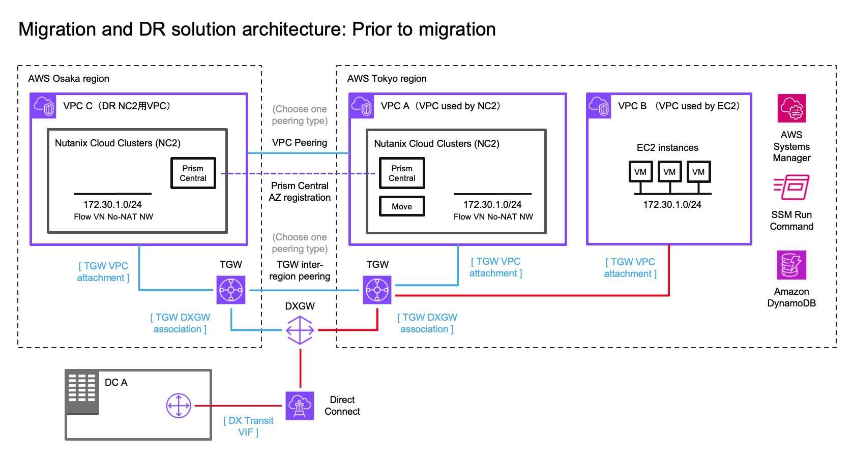
In this step we prepare for the migration from EC2 to NC2. The initial state of the network, the workloads and the route to the 172.30.1.0/24 network is as illustrated by the red line in the below diagram.
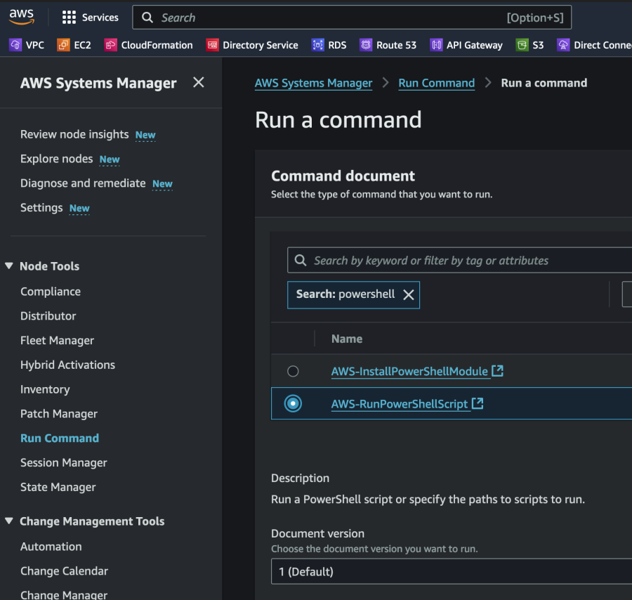
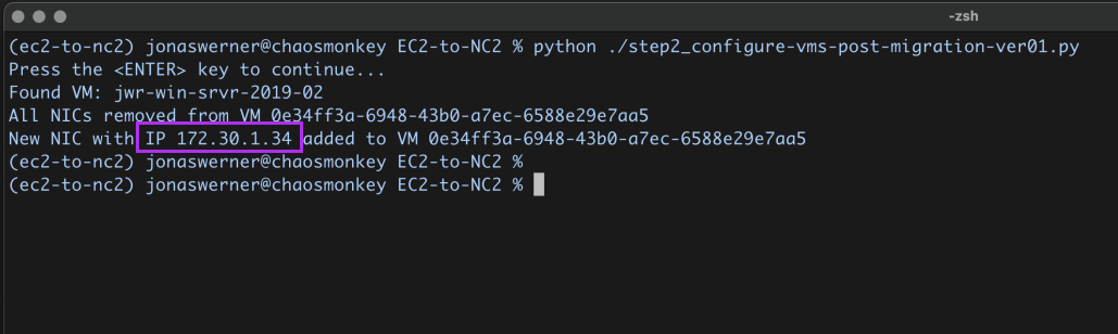
To start with we gather information about the EC2 instances and store that info in DynamoDB. In the name of efficiency we use the SSM Run command to execute the PowerShell script. This makes it easy to get this done in a single go (or two “goes” if we do both Windows and Linux workloads). We test with a single Windows 2019 Server EC2 instance in this example.
First create a DynamoDB table to hold this information. Nothing special is required for this table as long as it is accessible to SSM as it runs the script. We need to give the IAM role used when running SSM commands access to DynamoDB of course, so we add the following permissions to the standard SSM role:
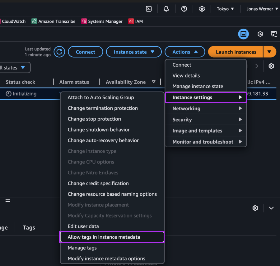
In order to collect the instance name from meta data we enable the “Allow tags in instance metadata” setting in the EC2 console. This is important as we will use the “Name” tag in EC2 as the Key to look up the instance in NC2 post-migration. Of course other methods could be used – most obviously the name of the instance itself. However in this case we use the EC2 name tag, as this is also how the VM will show up in NC2 post migration.
The we execute the script on our instances through the SSM Run command as follows
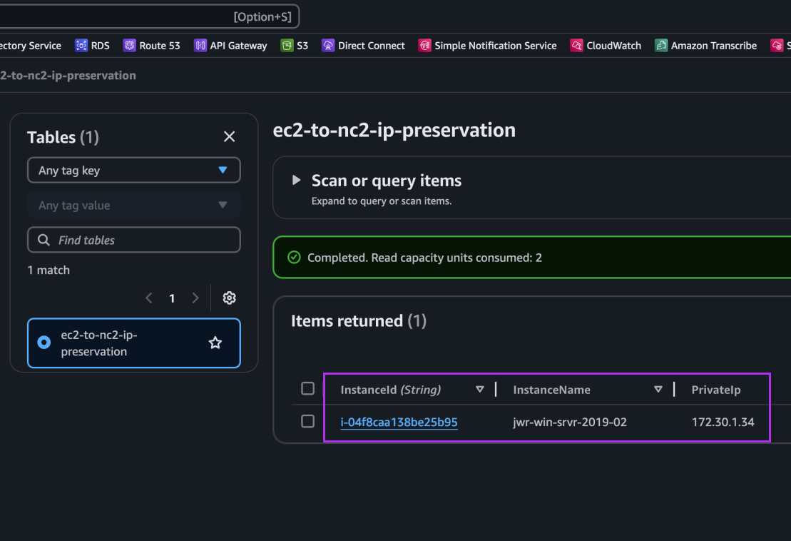
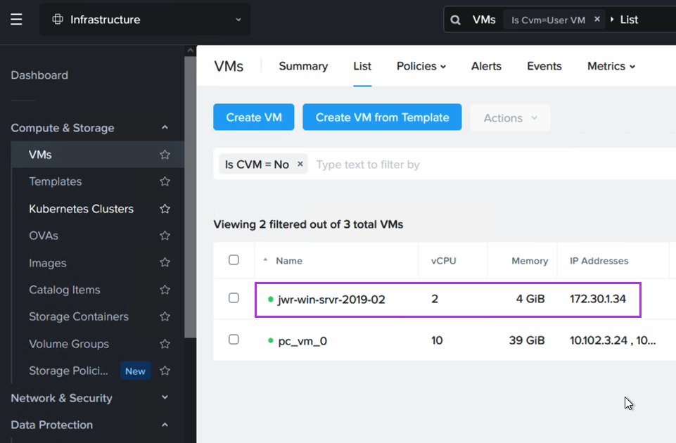
After execution we can see an entry for our Windows EC2 instance showing its instance ID, hostname and IP address: 172.30.1.34. This is the IP we want to retain.
That’s all for this section. Next we perform the migration from EC2 to NC2.
Step 2: Migrating from EC2 to NC2
For the migration we have deployed Nutanix Move on the NC2 cluster. We have also created an FVN overlay no-NAT network with the same CIDR as the subnet the EC2 instance is connected to, although the DHCP range is set to avoid any of the IPs currently used by instances on that subnet.
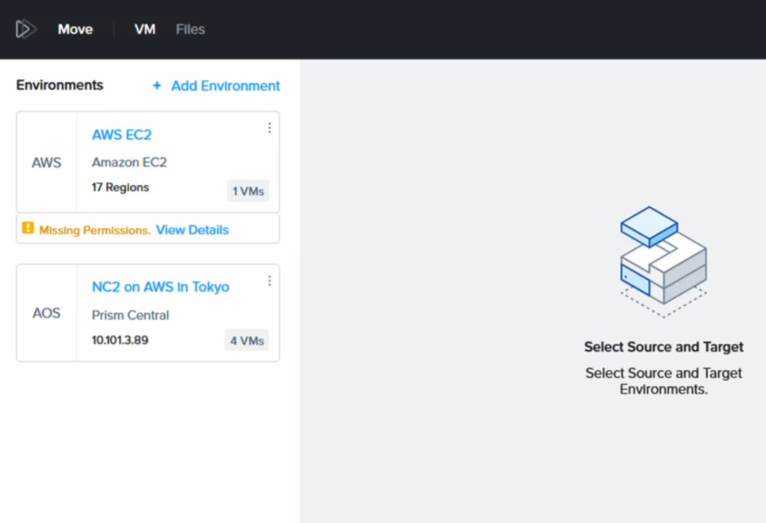
Move has the NC2 cluster and the AWS environment added in as migration sources / targets.
It complains about “missing permissions” but this is because we have only given it permission to migrate FROM EC2, not TO EC2. Since that is all we want to do, this is fine. Please refer to the Move manual for details on the AWS IAM policy required depending on your use case.
Post migration the VM will have a different IP address (taken from the DHCP range on the FVN subnet it is connected to).
We use a Python script in the next section to revert the IP address to what it was while running as an EC2 instance.
Step 3: Revert the IP address to match what the EC2 instance had originally
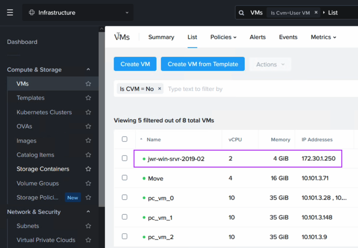
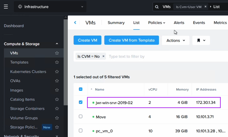
Now we execute a Python script which will look up the instance name in DynamoDB, match it with the VM name in NC2 and then remove and re-create the network interface using the Prism Central API. The new interface will have the original IP configured as a static address.
The script can be downloaded from GitHub here. Please export the Prism Central username and password as environment variables to run the script. Also update the Prism Central IP and the subnet name to match the one used in your environment as well as the AWS region and the DynamoDB table name.
After running the script we can now verify that the VM has received its original IP address. Note that since we have replaced the NIC in this process, the IP is the same as before, but the MAC address will have changed.
Routing after migration from EC2 to NC2 in Tokyo
Now that the VM exists on NC2 we need to update our routing to ensure that traffic is directed to this VM and not the original EC2 instance (which has now been shut down by Move after the migration).
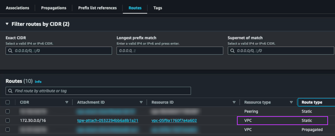
To do this we disconnect the EC2 VPC from the TGW and add the subnet as a static route in the TGW, this time pointing to the NC2 VPC rather than the EC2 VPC. The subnet should already exist as an “Allowed prefix” on the DXGW, so that part can be left as-is.
The attachments highlighted in red shows the active route to the 172.30.1.0/24 subnet, which has now been changed to point to the NC2 VPC. Since the subnet is a FVN no-NAT subnet it will show up in the NC2 VPC route table.
Wrapping up the migration part
Now our EC2 instance has been migrated to NC2. Its IP address is intact and since we have updated the routing between AWS and the on-premises DC, the on-prem users can access the migrated instances just like they normally would. In fact, apart from the maintenance window for the migration, VM power-up on NC2 and the routing switch, they are unlikely to notice that their former EC2 instance is now running on another platform.
Configuring DR between the Tokyo and Osaka NC2 clusters
At this point all we have left to do is set up the DR configuration between the two Nutanix clusters in Tokyo and Osaka. Since DR is a built-in component, this is very straight forward. We link the two Prism Central instances and of course create the FVN overlay network on the Osaka side as well to ensure we can keep the same CIDR range also after failover.
After enabling Disaster Recovery we can easily create the DR plan through Prism Central
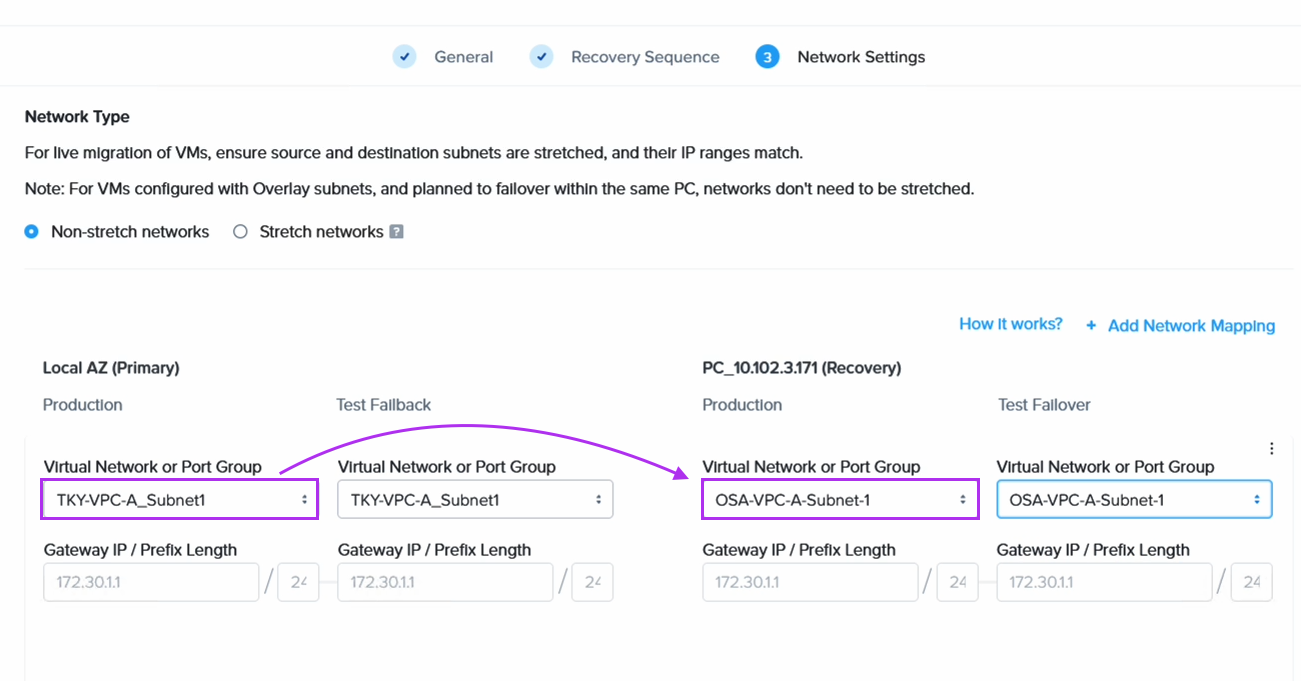
When we create the DR plan we set the VMs on the Tokyo network to fail over to its equivalent on the Osaka DR site
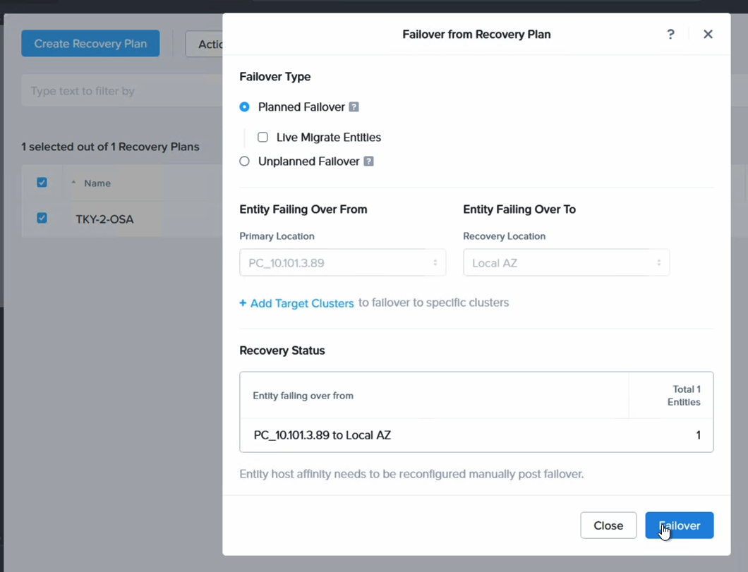
Finally we proceed to fail over our VM from NC2 in Tokyo to NC2 in Osaka
After failing over we can confirm that the VM is not only powered up in Osaka, but that it has also retained the IP address, as expected.
Updating the routing to point to Osaka rather than Tokyo
After failing over from Tokyo to Osaka we need to also update the routes pointing to the 172.30.1.0/24 network by modifying the TGW in Osaka. From a diagram perspective it will look like follows.
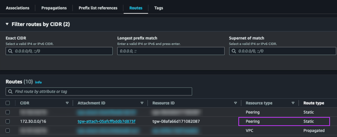
On the Osaka TGW we create a static route to the 172.30.0.0/16 network pointing to the Osaka NC2 VPC
We also update the static route on the Tokyo TGW which points to the local NC2 VPC and instead set it to point to the peering connection to Osaka
Results and wrap-up
With these routing changes implemented it is now possible for users on the on-premises DC to continue to access the very same VMs with the very same IP addresses. This possible is even after those workloads have been migrated from EC2 to NC2 in Tokyo and then further having been failed over with a DR plan from Tokyo region to Osaka region.
Hope that was helpful! Please reach out to your local Nutanix representative for discussions if this type of solution is of interest. Thank you for reading!