If one tries to install ESXi on a server equipped with network cards which are not on the official VMware HCL (Hardware Compatibility List), the installer will stop at the network card detection step and refuse to continue with a happy “No network adapters detected”. This is very common for those of us running VMware home labs on non-enterprise hardware.
However, VMware does provide additional network drivers in the shape of Flings. They can be downloaded but how does one create a custom ESXi installer ISO file using those drivers?
To make this process easy and fully automated, I created a PowerShell script which downloads the ESXi image (pick whichever version required) and also the community network drivers as well as the USB network driver fling. It then bundles everything up into an ISO file which can then be written to a USB stick or CD / DVD for installation.
What if you need a different version of ESXi or different drivers?
No problems, the script can be customized to accommodate this as well. Please refer to the YouTube video below for details.
This is a quick, practical and unofficial guide showing how to use NSX Autonomous Edge to do L2 extension / stretching of VLANs from on-prem to VMware Cloud on AWS.
Note: The guide covers how to do L2 network extension using NSX Autonomous Edge. It doesn’t cover the deployment or use of HCX or HLM for migrations.
Why do L2 extension?
One use case for L2 extension is for live migration of workloads to the cloud. If the on-prem network is L2 extended / stretched there will be no interruption to service while migrating and no need to change IP or MAC address on the VM being migrated.
Why NSX Autonomous Edge?
VMware offers a very powerful tool – HCX (Hybrid Cloud Extension) to make both L2 extension and migrations of workloads a breeze. It is also provided free of charge when purchasing VMware Cloud on AWS. Why would one use another solution?
No need to have a vSphere Enterprise Plus license
Because L2 extension with HCX requires Distributed vSwitches and those in turn are only available with the top level vSphere Enterprise Plus license. Many customers only have the Standard vSphere license and therefore can’t use HCX for L2 extension (although they can use it for the migration itself which will be shown later in this post). NSX Autonomous Edge works just fine with standard vSwitches and therefore the standard vSphere license is enough
Active / standby HA capabilities
Because HCX doesn’t include active / standby redundancy. Sure, you can enable HA and even FT on the cluster, but FT maxes out at 4 VMs / cluster and HA might not be enough if your VMs are completely reliant on HCX for connectivity. NSX Autonomous Edge allows two appliances to be deployed in a HA configuration.
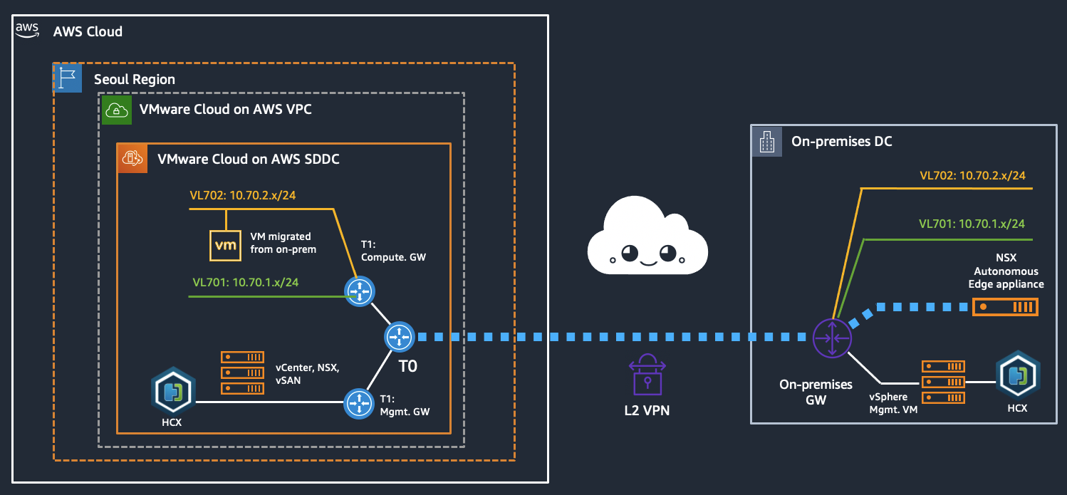
Configuration diagram (what are we creating?)
We have an on-prem environment with multiple VLANs, two of which we want to stretch to VMware Cloud on AWS and then migrate a VM across, verifying that it can be used throughout the migration. In this case we use NSX Autonomous Edge for the L2 extension of the networks while using HCX for the actual migration.
End state, prior to removing on-prem networks
Prerequisites
A deployed VMware Cloud on AWS SDDC environment
Open firewall rules on your SDDC to allow traffic from your on-prem DC network (create a management GW firewall rule and add your IP as allowed to access vCenter, HCX, etc.)
If HCX is used for vMotion: A deployed HCX environment and service mesh (configuration of HCX is out of scope for this guide)
Summary of configuration steps
Enable L2 VPN on your VMC on AWS SDDC
Download the NSX Autonomous Edge appliance from VMware
Download the L2 VPN Peer code from the VMC on AWS console
Create two new port groups for the NSX Autonomous Edge appliance
Deploy the NSX Autonomous Edge appliance
L2 VPN link-up
Add the extended network segments in the VMC on AWS console
VM migration using HCX (HCX deployment not shown in this guide)
Video of the setup process
As an alternative / addition to the guide below, feel free to refer to the video below. It covers the same steps but quicker and in a slightly different order. The outcome is the same however.
Enable L2 VPN on your VMC on AWS SDDC
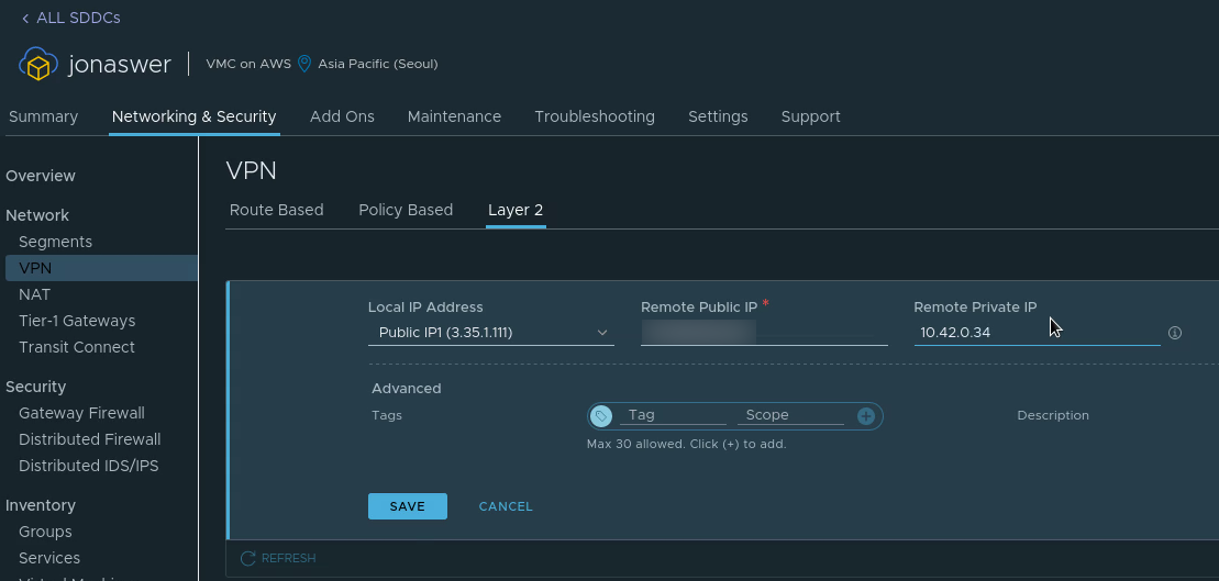
Navigate to “Networking & Security”, Click “VPN” and go to the “Layer 2” tab
Click “Add VPN tunnel”
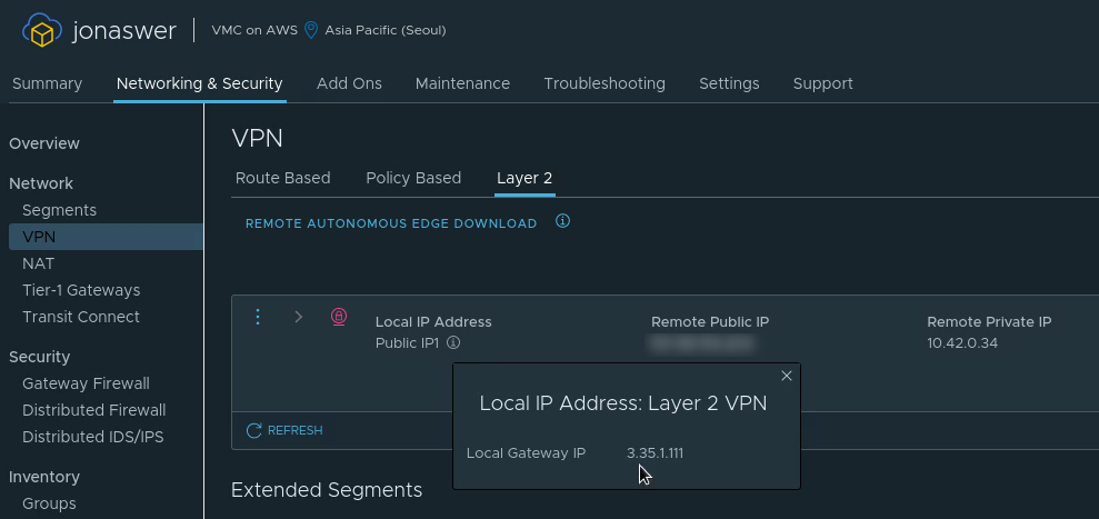
Set the “Local IP address” to be the VMC on AWS public IP
Set the “Remote public IP” to be the public IP address of your on-prem network
Set the “Remote private IP” to be the internal IP you intend to assign the NSX Autonomous Edge appliance when deploying it in a later step
Configuring the L2 VPN server side in VMC on AWS
Download the NSX Autonomous Edge appliance
After deploying the L2 VPN in VMC on AWS there will be a pop-up with links for downloading the virtual appliance files as well as a link to a deployment guide
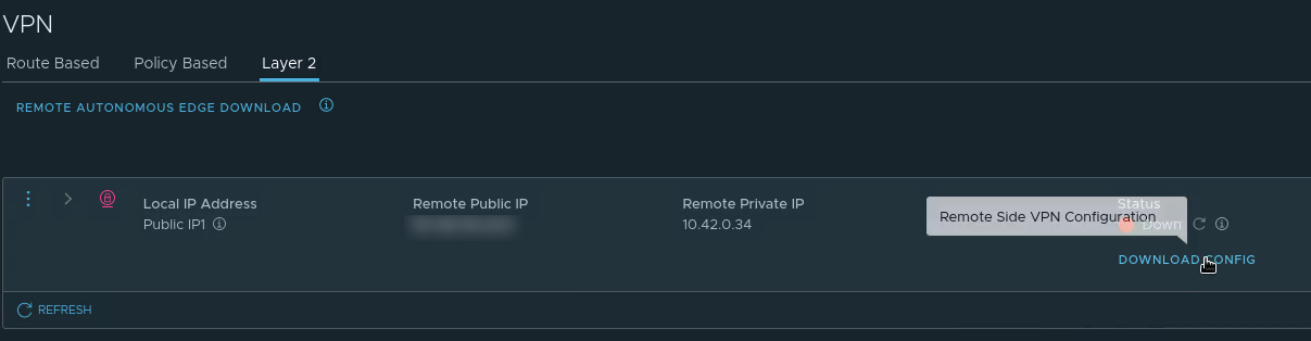
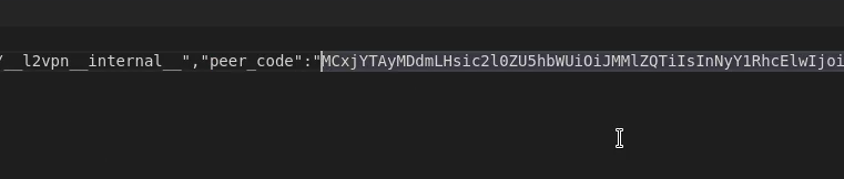
Download the L2 VPN Peer code from the VMC on AWS console
Download the Peer code for your new L2 VPN from the “Download config” link on the L2 VPN page in the VMware Cloud on AWS console. It will be available after creating the VPN in the previous step and can be saved as a text file
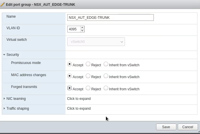
Create two new port groups for the NSX Autonomous Edge appliance
This is for your on-prem vSphere environment. The official VMware deployment guide suggests creating a port group for the “uplink” and another for the “trunk”. The uplink provides internet access through which the L2 VPN is created. The “trunk” port connects to all VLANs you wish to extend.
In this case I used an existing port group with internet access for the uplink and only created a new one for the trunk.
For the “trunk” port group: Since this PG need to talk to all VLANs you wish to extend, please create it under a vSwitch with uplinks which has those VLANs tagged.
A port group would normally only have a single VLAN set. How do we “catch them all”? Simply set “4095” as the VLAN number. Also set the port group to “Accept” the following:
Promiscuous mode
MAC Address changes
Forged transmits
Deploy the NSX Autonomous Edge appliance
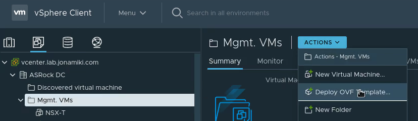
The NSX Autonomous Edge can be deployed as an OVF template. In the on-prem vSphere environment, select deploy OVF template
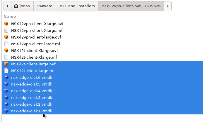
Browse to where you downloaded the NSX Autonomous Edge appliance from the VMware support page. The downloaded appliance files will likely contain several appliance types using the same base disks. I used the “NSX-l2t-client-large” appliance:
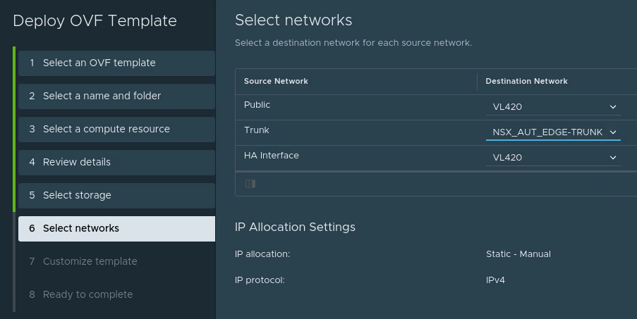
For the network settings:
Use any network with a route to the internet and good throughput as the “Public” network.
The “Trunk” network should be the port group with VLAN 4095 and the changed security settings we created earlier.
The “HA Interface” should be whatever network you wish to use for HA. In this case HA wasn’t used as it was a test deployment, so the same network as “Public” was selected.
For the Customize template part, enter the following:
Passwords: Desired passwords
Uplink interface: Set the IP you wish the appliance to have on your local network (match with what you set for the “Remote Private IP” in the L2 VPN settings in VMC on AWS at the beginning)
L2T: Set the public IP address shown in VMC on AWS console for your L2 VPN and use the Peering code downloaded when creating the L2 VPN at the start.
Use the Public IP (“Local IP Address”) as the “Peer address” when deploying the appliancePeering code: Make sure to copy the whole thing. It often ends in equal marks and they have to be copied in too(!)Example of template customization for our test deployment
Enable TCP Loose Setting: To keep any existing connections alive during migration, check this box. For example, if you have an SSH session to the VM you want to migrate which you wish to keep alive.
The Sub interfaces: This is the most vital part and the easiest place to make mistakes. For the Sub interfaces, add your VLAN number followed by the tunnel ID in brackets. This will assign each VLAN a tunnel ID and we will use it on the other end (the cloud side) to separate out the VLANs.
They should be written as: VLAN(tunnel-ID). Example for VLAN 100 and tunnel ID 22 would look like this: 100(22). For our lab we extend VLANs 701 and 702 and will also assign them tunnel IDs which match the VLAN number. For multiple VLANs, use comma followed by space to separate them. Don’t use ranges. Enter each VLAN with its respective tunnel ID individually.
HA index: Funny detail – HA is optional but if you don’t set the HA index on your initial appliance anyway it won’t boot. Even if you don’t intend to use HA, please set this to “0”. HA section is not marked as “required” by the wizard when deploying, so it is fully possible to deploy a non-functioning appliance.
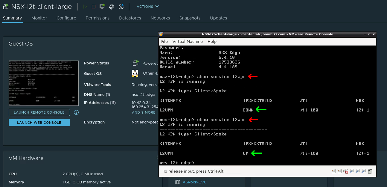
L2 VPN link-up
The L2 VPN tunnel will connect automatically using the settings provided when deploying the appliance. Open the console of the L2 VPN appliance, log in with “admin / <your password>” and issue the command “show service l2vpn”. After a moment the link will come up (provided that the settings used during deployment were correct).
Viewing the L2 VPN tunnel status from the appliance console in vCenter on-prem
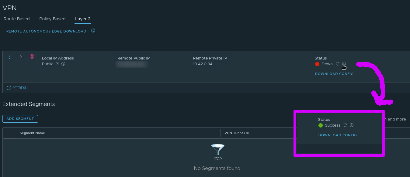
In the VMC on AWS console the VPN can also be seen to change status from “Down” to “Success”
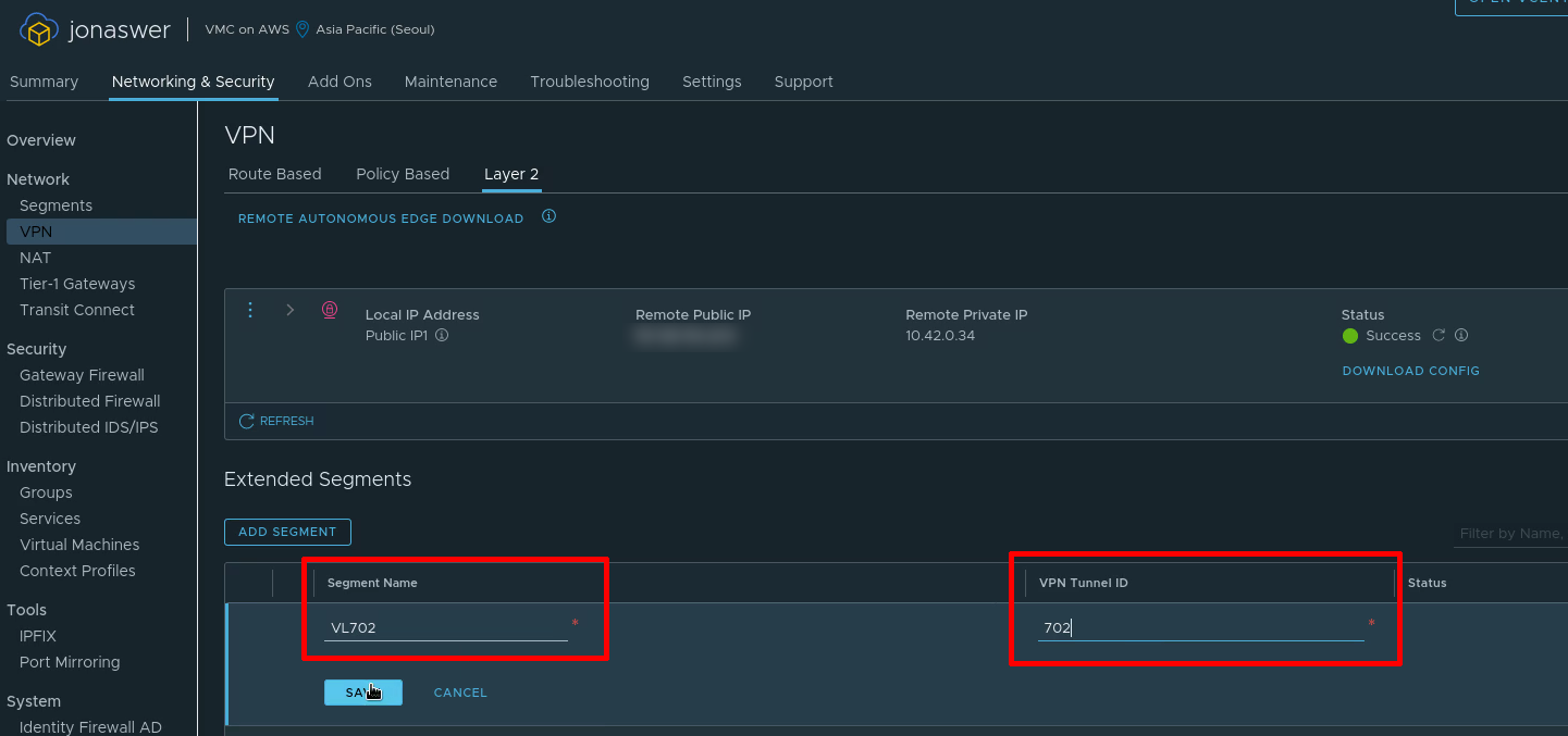
Add the extended network segments in the VMC on AWS console
Under the L2 VPN settings tab in the VMC on AWS console it is now time to add the VLANs we want to extend from on-prem. In this example we will add the single VLAN 702 which we gave the tunnel ID “702” during the NSX Autonomous Edge deployment
Adding the VLANs we wish to extend from on-prem in the VMC on AWS console
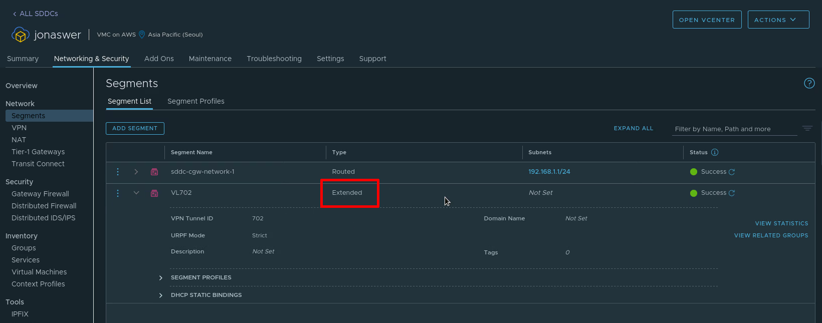
The extended network can now be viewd under “Segments” in the VMC on AWS console and will be listed as type “Extended”
VM migration using HCX
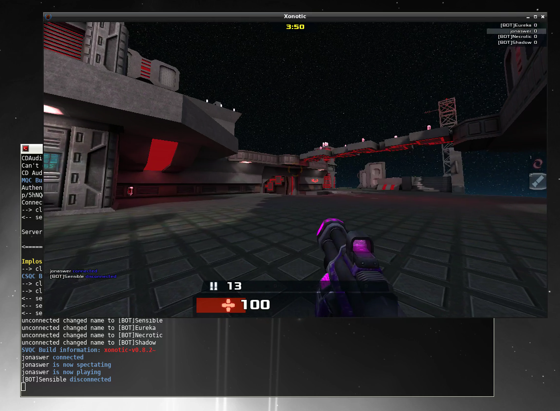
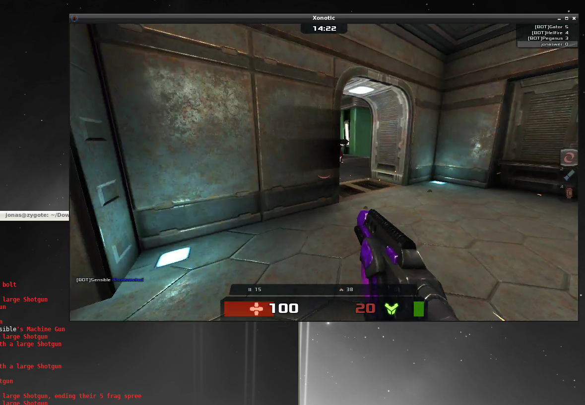
Now the network has been extended and we can test it by migrating a VM from on-prem to VMC on AWS. To verify if it works we’ll be running Xonotic – an open source shooter – on the VM and run a game throughout the migration.
Starting a nice round of Xonotic deathmatch from our local machine to the VM we are about to migrate to the cloud
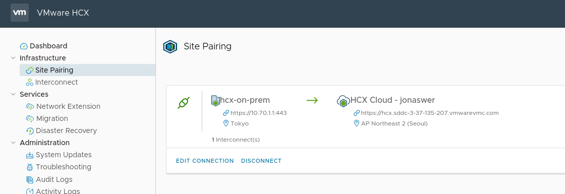
Verifying that our HCX link to the VMC on AWS environment is up
Starting the migration by right-clicking the VM in our local on-prem vCenter environment
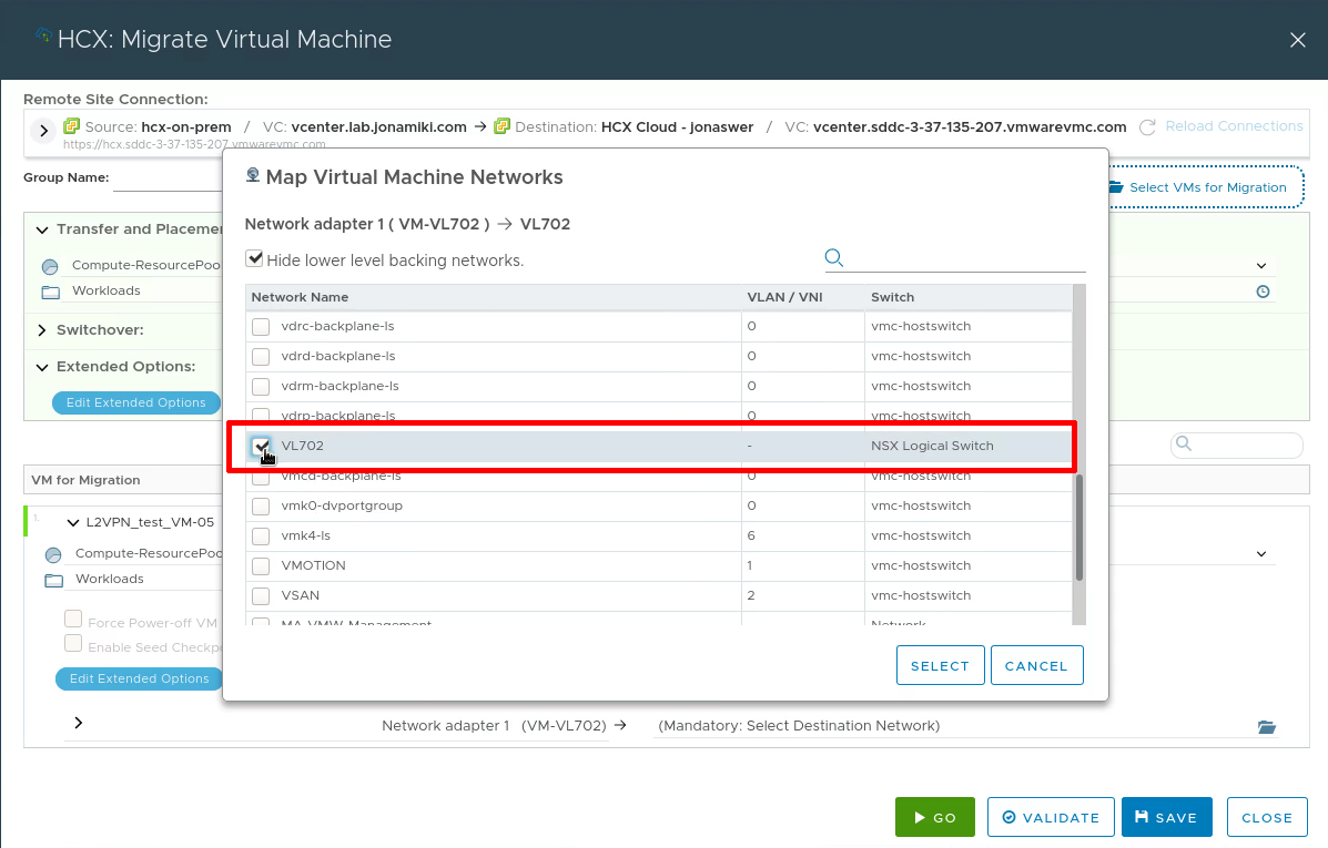
Selecting our L2 extended network segment as the target network for the virtual machine
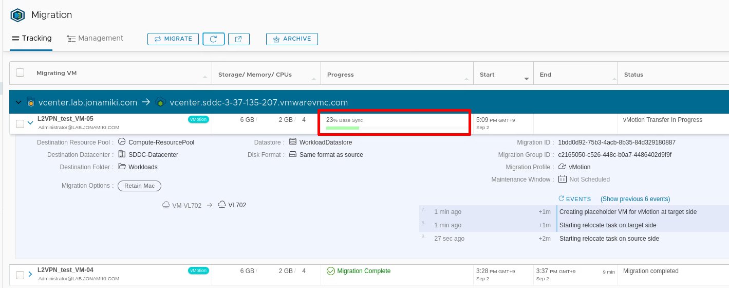
Monitoring the migration from the HCX console
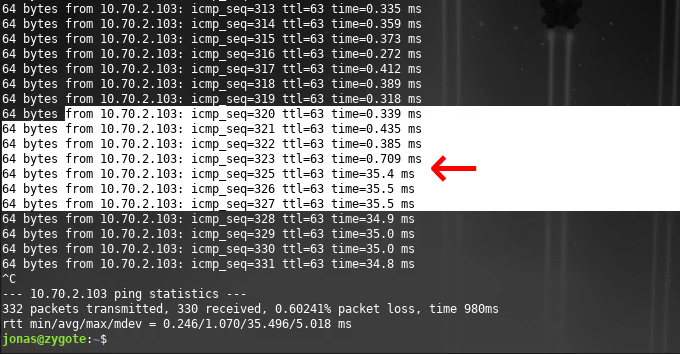
If the VM is pinged continuously during migration: Once the migration is complete the ping time will go from sub-millisec to around 35ms (migrating from Tokyo to Seoul in this case)
Throughout migration – and of course after the migration is done – our Xonotic game session is still running, albeit with a new 35ms lag after migration 🙂
Conclusion
That’s it – the network is now extended from on-prem. VMs can be migrated using vMotion via HCX or using HLM (Hybrid Linked Mode) with their existing IPs and uninterrupted service.
Any VMs migrated can be pinged throughout migration and if the “Enable TCP loose Setting” was checked any existing TCP sessions would continue uninterrupted.
Also, any VMs deployed to the extended network on the VMC on AWS side would be able to use DHCP, DNS, etc. served on-prem through the L2 tunnel.
if you followed along this far: Thank you and I hope you now have a fully working L2 extended network to the cloud!
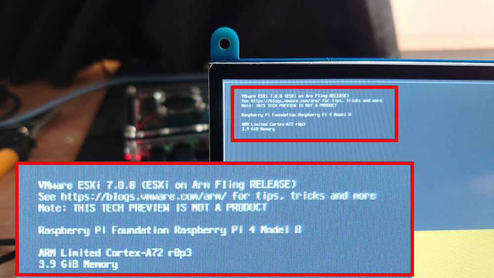
Absolutely delighted to be able to run the ESXi fling for Raspberry Pi. Really cool to see ARM being supported at least for the hypervisor. If some day vCenter would also be available in an ARM flavor it’d be pretty cool.
Not officially supported for actual workloads 😀 It’s certainly possible to run ARM VMs though.
Photon OS is a VMware initiative to create a lightweight Linux based OS with container support. I have to admit my initial reaction to Photon OS was: “y tho?”
It’s a reasonable reaction. There are MANY Linux based OS options out there already and essentially all of them have container support. The reason for creating Photon OS would seem to be that VMware wants their own rubber-stamped Linux OS as part of an ecosystem under their control.
Photon OS’s redeeming feature is the fact that it’s really lightweight. Not as lightweight as Ubuntu Core though. Photon OS for Raspberry Pi weighs in at 512Mb while Ubuntu Core is 450Mb. Still, given the influence of VMware in virtualization and their (our) inroads into IoT / M2M with Pulse, it’s likely that Photon OS will take off eventually.
Currently the main barrier to widespread adoption of Photon OS is a lack of commercial support. At the moment it is simply available as an unsupported download from GitHub (here). This could change in the future though and in that case we may see it being utilized more broadly and also outside the lab environments it is currently inhabiting.
Note that unlike Raspbian, which is 32bit, Photon OS is a 64bit operating system. That too may be something that’ll help float the boat for some.
Getting started with Photon OS on the Raspberry Pi
Deflate the zx compressed image and save to a micro-SD card:
tar xf photon-rpi3-3.0-26156e2.tar.xz
cd rpi3/
sudo dd if=photon-rpi3-3.0-26156e2d.raw of=/dev/mmcblk0 bs=4M;sudo sync
In this example the SD card device is /dev/mmcblk0. This may differ on other systems of course. Please check with “lsblk” or so and please do be careful. Linux / Unix folks don’t refer to dd as “Disk Destroyer” for nothing.
Boot the Raspberry Pi and log in. The default credentials are: root / changeme
DHCP and SSH are both enabled by default and should make it possible to access the Pi across the network if using a wired connection (I haven’t tried though). With a Raspberry Pi it’s likely a wireless connection would be more convenient however. Configuring Wi-Fi is easy and is described in the section that follows.
Photon OS Wi-Fi configuration
There are a few steps to go through for Wi-Fi connectivity but it’s not difficult.
Start the wpa_supplicant service
systemctl start wpa_supplicant@wlan0
Enable the wpa_supplicant service (so it starts with the Pi)
systemctl enable wpa_supplicant@wlan0
Check the service status
systemctl status wpa_supplicant@wlan0
Edit the dhcp settings to get DHCP for wlan0 and not eth0
Photon OS comes in a few different sizes and in the larger ones both Docker and Kubernetes are preinstalled. Not so with the Raspberry Pi version though, so we need to install Docker manually.
Packages are installed with either “yum” or “tdnf”. Docker is available from tdnf so we’ll use that to run the install below.
Refresh the cache but don’t update the packages
We need to refresh the tdnf cache to find the docker package. However, this process can also be used to update all packages. I found that this breaks Wi-Fi. So, if you use Wi-Fi I recommend:
root@photon-rpi3 [ ~ ]# tdnf update

Then select "n" to just refresh the cache without updating any packages.
root@photon-rpi3 [ ~ ]# docker pull hello-world
Using default tag: latest
latest: Pulling from library/hello-world
3b4173355427: Pull complete
Digest: sha256:2557e3c07ed1e38f26e389462d03ed943586f744621577a99efb77324b0fe535
Status: Downloaded newer image for hello-world:latest
root@photon-rpi3 [ ~ ]# docker run hello-world

Hello from Docker!
This message shows that your installation appears to be working correctly.

To generate this message, Docker took the following steps:
 1. The Docker client contacted the Docker daemon.
 2. The Docker daemon pulled the "hello-world" image from the Docker Hub.
    (arm64v8)
 3. The Docker daemon created a new container from that image which runs the
    executable that produces the output you are currently reading.
 4. The Docker daemon streamed that output to the Docker client, which sent it
    to your terminal.

To try something more ambitious, you can run an Ubuntu container with:
 $ docker run -it ubuntu bash

Share images, automate workflows, and more with a free Docker ID:
 https://hub.docker.com/

For more examples and ideas, visit:
 https://docs.docker.com/get-started/

root@photon-rpi3 [ ~ ]#
That’s all! Photon OS is installed, Wi-Fi configured, Docker installed and verified. Ready to rock.
Automating VM power control over the command line can be very useful. Especially to simplify test scenarios when tens or hundreds of VM’s are used. A couple of simple examples below.
Unfortunately the commands for powering on and off are completely different. This means we have two separate scripts for each task:
Powering on: List all VM’s so we can find the ones we want:
Grep for the ones we are interested in:
Print only their IDs:
Because we’re pedantic – sort them in correct order – just in case:
Run a loop to power them on:
Powering off: List all the processes:
By default esxcli lists the information on separate lines which makes scripting close to impossible. Therefore we use the –formatter option to list the output in CSV format.
To enable AWK we replace spaces with % (for example) and commas with spaces: