
In spring of 2021 I wanted a proper VMware lab setup at home. The primary reason was, and still is, having an environment in which to learn and experiment with the latest VMware and AWS solutions. I strongly believe that actual hands-on experience is the gateway to real knowledge, despite how well the documentation may be written.
To that end I went about listing up what would be needed to make this dream of a home lab come true. The lack of space meant that the setup would end up in my bedroom and therefore needed to be quiet. That removed most 2nd hand enterprise servers from the list. Possibly with the exception of the VRTX chassis from Dell, which I would still REALLY want for a home lab, but it’s way to expensive – even 2nd hand.
Requirements:
- As compatible with the VMware HCL as possible (as-is or via Flings)
- Quiet (no enterprise servers)
- Energy efficient
- Not too big (another nail in the coffin for full-depth 19″ servers)
- Reasonable performance
- Ability to run vSAN
- 10Gbps networking
Server hardware
Initially I considered the Intel NUCs and Skull / Ghost Canyon mini-PCs as these are very popular among home-lab enthusiasts. However, the 10Gbps requirement necessitated a PCIe slot and the models supporting this from Intel are very expensive.
The SuperMicro E300-9D was also on the list but they too tend to get expensive and a bit hard to get on short notice where I live.
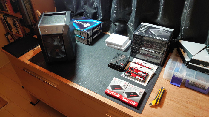
Therefore, going with a custom build sounded more and more in line with what would work for this setup. In the end I settled on the below. The list contain all the parts used for the ESXi nodes, minus the network cards which are listed separately in the networking section below.
| Part | Brand | Cost (JPY) | |
| Mobo | ASRock Intel H410M-ITX/ac I219V | 12,980 | link |
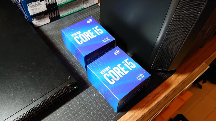
| CPU | Core i5 10400 BOX (6c w. graphics) | 20,290 | link |
| RAM | TEAM DDR4 2666Mhz PC4-21300 (2×32) | 33780 | link |
| m.2 cache | WD Black 500Gb SSD M.2-2280 SN750 | 9,580 | link |
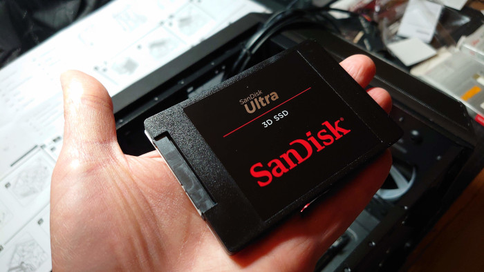
| 2.5″ drive | SanDisk 2.5″ SSD Ultra 3D 1TB | 13,110 | link |
| PSU | Thermaltake Smart 500W -STANDARD | 4,756 | link |
| Case | Cooler Master H100 Mini Tower | 7,023 | link |
| Total | 101,519 |
Mainboard and case
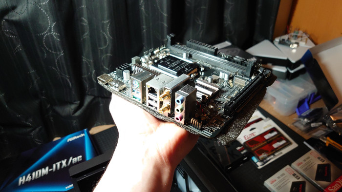
The choice of mainboard came down to the onboard network chipset. It had to be possible to run the ESXi installer and it won’t work if it can’t find the network. Initially I only had the onboard NIC and no 10Gbps cards. Unfortunately the release of vSphere version 7.x restricted the hardware support significantly. This time I was going to make an AMD build, but most of their mainboards come with Realtek onboard NICs and they are no longer recognized by the ESXi installer. Another consideration was size and expansion options. An ITX formfactor meant that the size of the PC case could be reduced while still having a PCIe slot for a 10Gbps NIC.
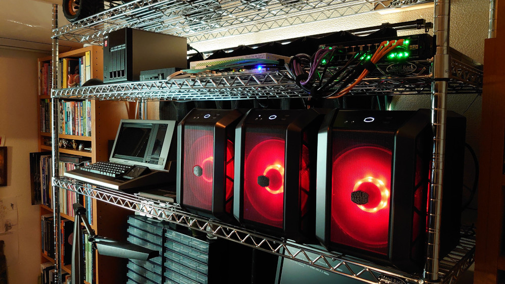
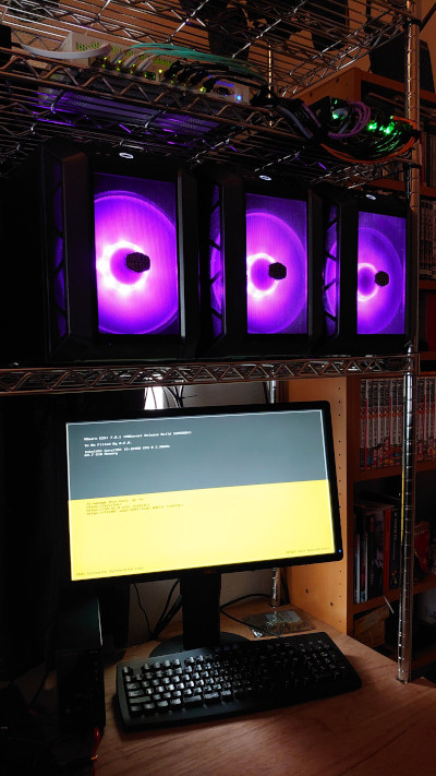
The Cooler Master H100 case has a single big fan which makes it pretty quiet. Its small size also makes it an ideal case for this small-footprint lab environment. It even comes with LEDs in the fan which are hooked up to the reset button on the case to switch between colors (or to turn it off completely).
CPU
Due to the onboard NIC support the build was restricted to an Intel CPU. Gen 11 had been released but Gen 10 CPUs were still perfectly fine and could be had for less money. Obviously, there was no plan to add a discreet GPU so the CPU also had to come with built-in graphics. The Core i5 10400 seemed to meet all criteria while having a good cost / performance balance.
Memory
The little ASRock H410M-ITX/ac mainboard supports up to 64Gb of RAM and I filled it up from the start. One can never have too much RAM. With three nodes we get a total of 192Gb which will be sufficient for most tasks. Likely there will come a day later when a single workload (looking at you NSX-T!!) will require more. This is the only area which I feel could become a limitation soon. For that day I’ll likely have to add a box with more memory specifically for covering that workload.
Storage
A vSAN environment was one of the goals for the lab and with an NVME PCIe SSD as the cache tier and a 2.5″ drive as the capacity tier this was accomplished. It was a bit scary ordering these parts without knowing if they would be recognized in vCenter as usable for vSAN, but in the end there was no issue at all. They were all recognized immediately and could be assigned to the vSAN storage pool.
For the actual ESXi install I was going to use a USB disk initially but ended up re-using some old 2.5″ and 3.5″ spinning rust drives for the hypervisor install. These are not part of the cost calculation above as I just used whatever was laying around at home. The cost of these is negligible though.
Network hardware
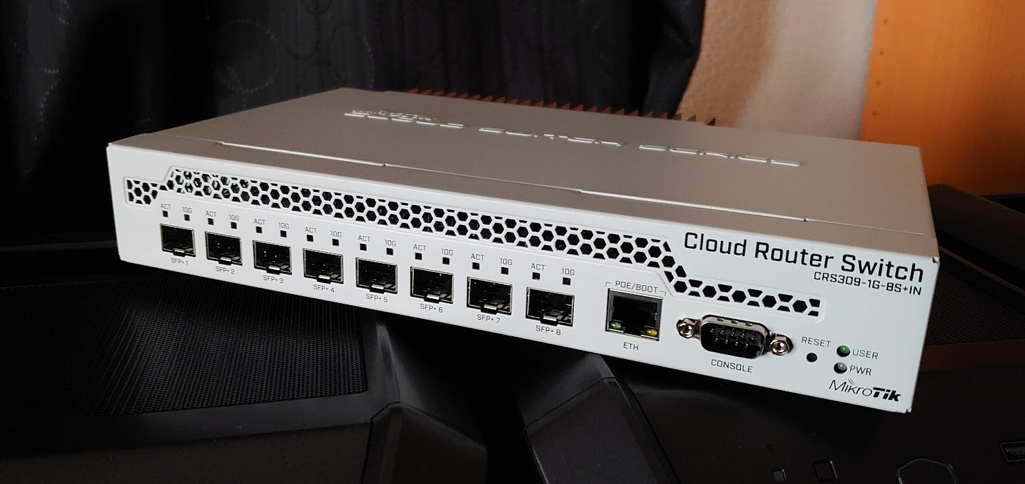
To ensure vSAN performance and to support the 10Gbps internet router uplink a 10Gbps managed switch was required. Copper ports become very expensive so SFP+ would be the way to go. Mikrotik has a good 8+1 port switch / router in their CRS309-1G-8S+IN model. In the end this was a good fit for the home lab because not only does it have 8x 10Gbps SFP+ ports, it is also fanless and the software support several advanced features, like BGP.
I’m still happy with the choice 6 months later. It’s a great switch but it took a while to get used to it. Most of us probably come from a Cisco or Juniper background. The configuration for the Mikrotik is completely different and won’t be intuitive for the majority of users.
On the server side I wanted something which would be guaranteed to work with ESXi, so a 10Gbps card which is on the HCL was a must. Intel has a lot of cards on the list and their X520 series can be found pretty easily. In the end I got three X520-DP2 (dual port) cards and they have worked perfectly so far.
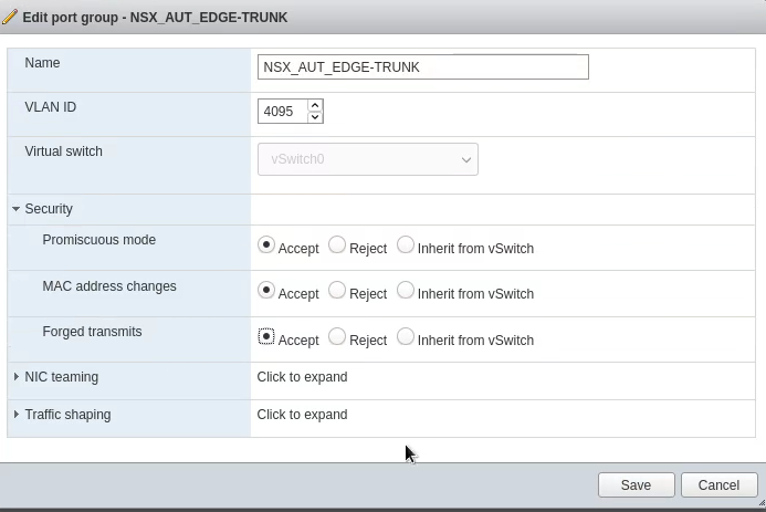
There is also a 1Gbps managed Dell x1026p switch to allow for additional networking options with NSX-T. With the Mikrotik 10Gbps switch there the Dell switch is more an addition for corner cases. It does help when attaching other devices which doesn’t support 10Gbps though.
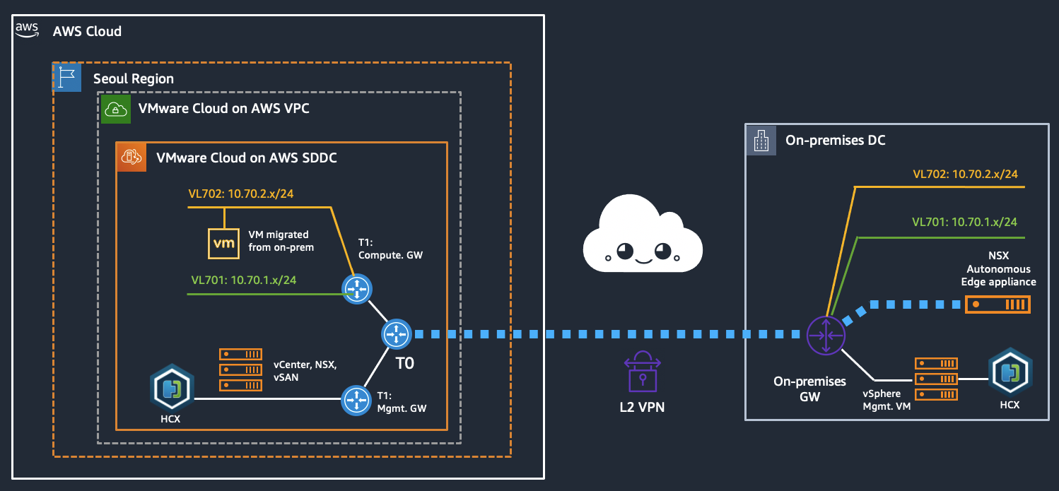
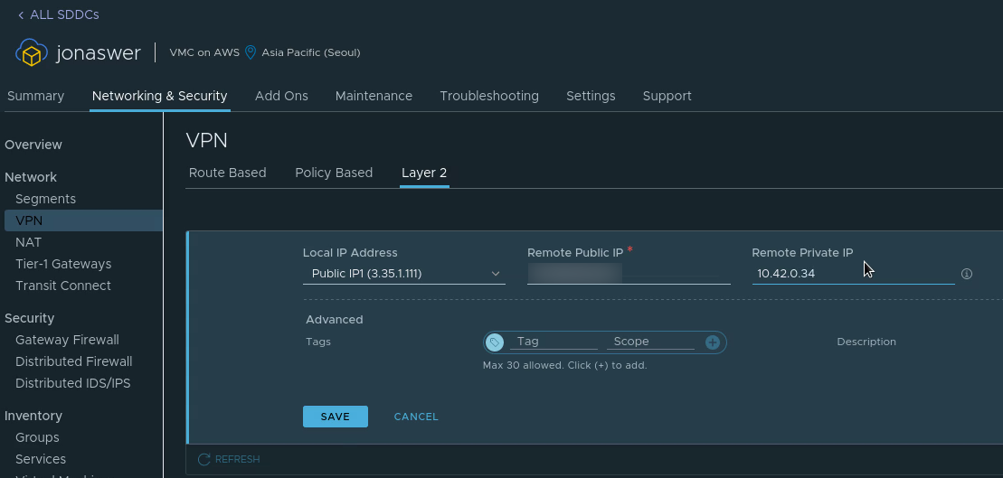
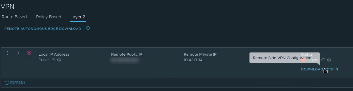
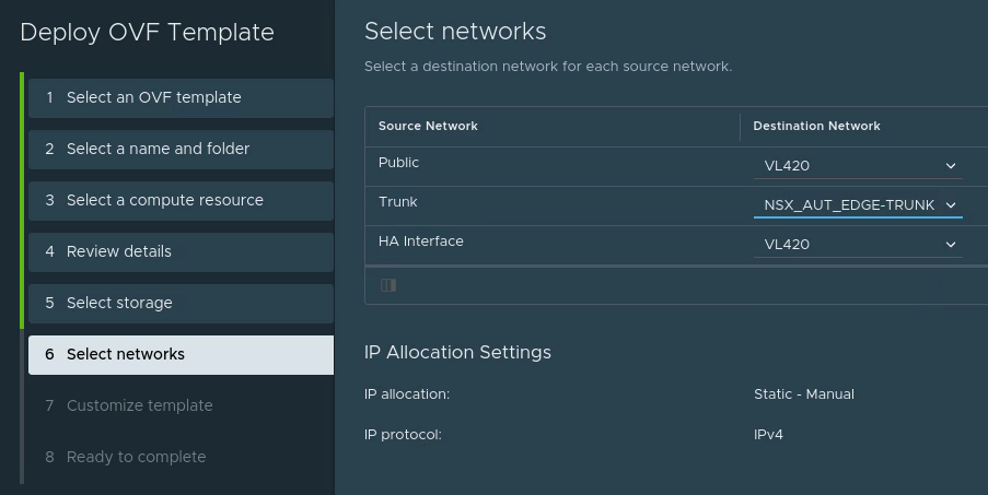
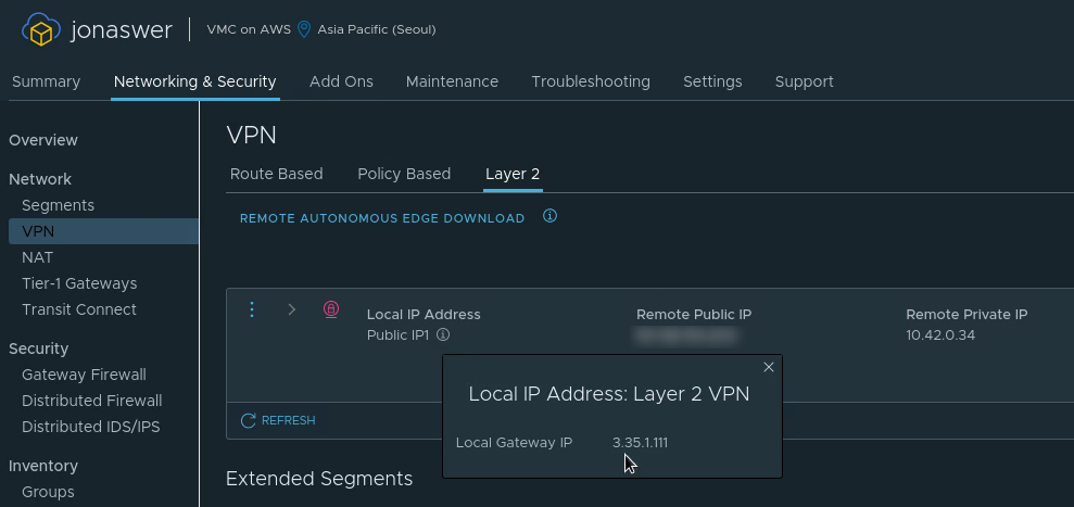
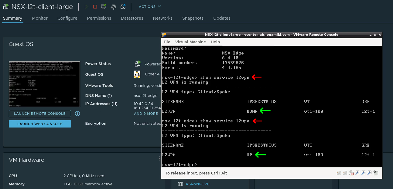
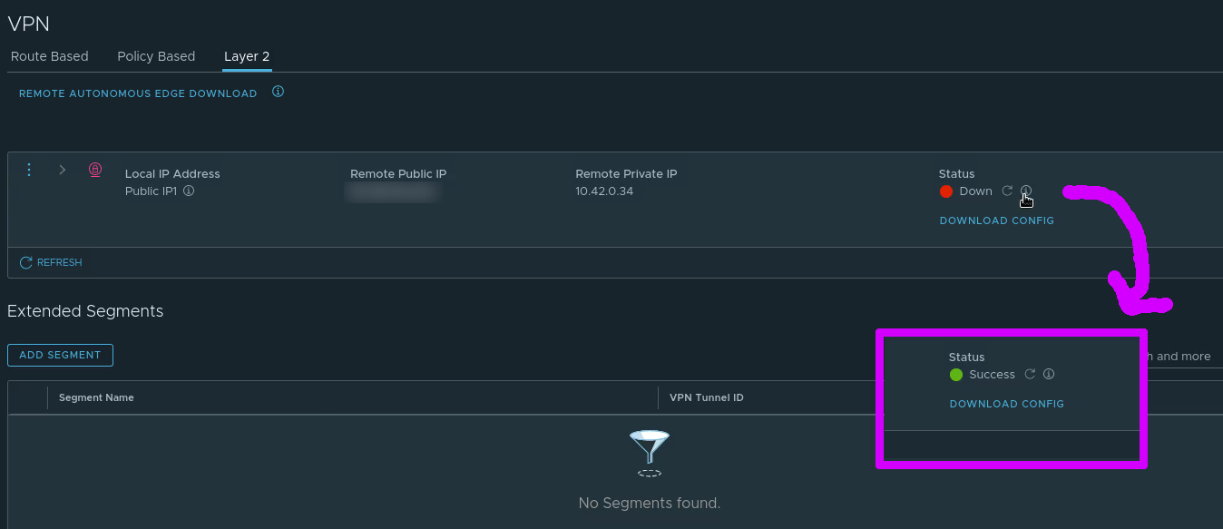
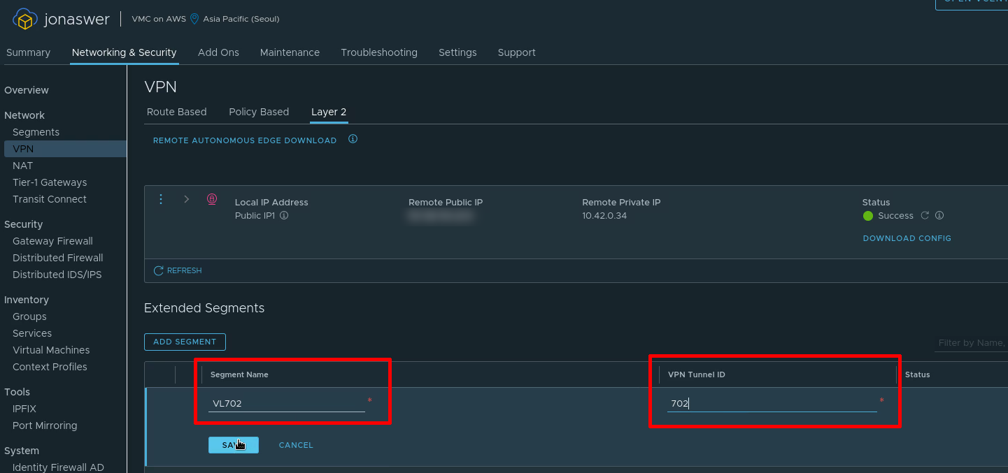
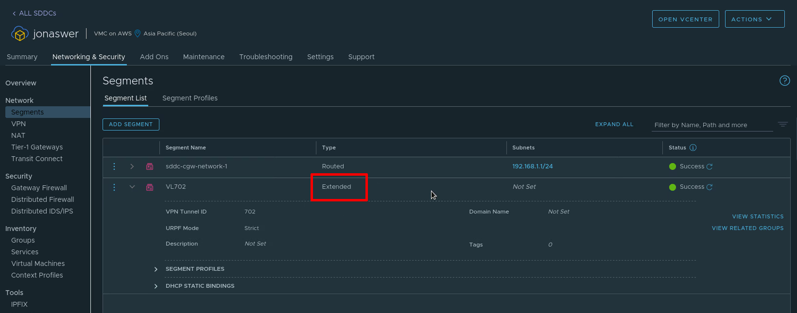
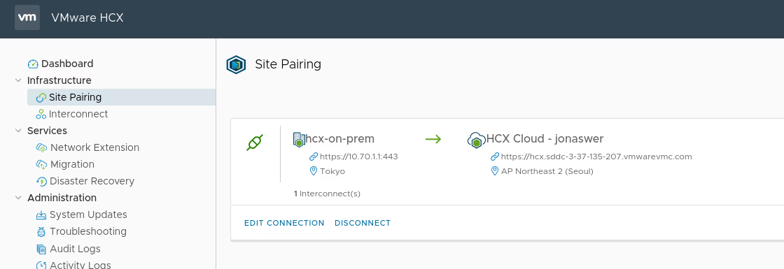
The Mikrotik has a permanent VPN connection to an AWS Transit Gateway and from there to various VPCs and sometimes the odd VMware Cloud on AWS SDDC.
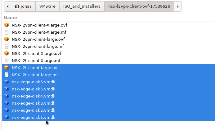
Installation media etc.
These servers still require custom installation media to be created for the installation to work. Primarily for the onboard Intel networking and the USB network Fling. An explanation for how to create custom media can be found here.
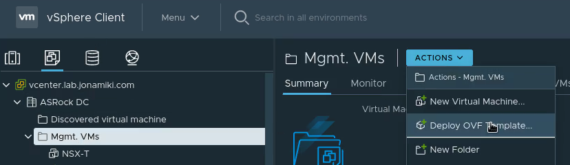
vCenter is hosted on an NFS share from a separate server. This is done so it could be on shared storage for the cluster while simultaneously being separate from the vSAN while the environment is being built.
ESXi is installed over PXE to allow for fully automated installations.
Conclusion
That’s it – a fully functional VMware lab. Quiet and with reasonably high performance. Also, RGB LEDs adds at least 20% extra performance – a bit like red paint on a sports car 😉