One of the great things about running a virtualized infrastructure on NC2 on AWS is the close proximity to all the cloud native services. One of those highly useful services is the AWS ELB or Elastic Load Balancer.
In this post we show how to get floating IP addresses from the VPC in which NC2 is located and to assign them to a number of web servers running as VMs on NC2. Then we create a Load Balancer target group and finally we create an Application Load Balancer (ALB) and attach it to the target group.
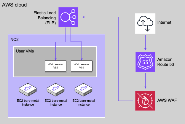
Architecture
In this blog post we only cover the deployment of the web servers and the load balancer, however, Route 53 can also be leveraged for DNS and AWS WAF for security and DDOS protection purposes as illustrated below
Preparing some web servers
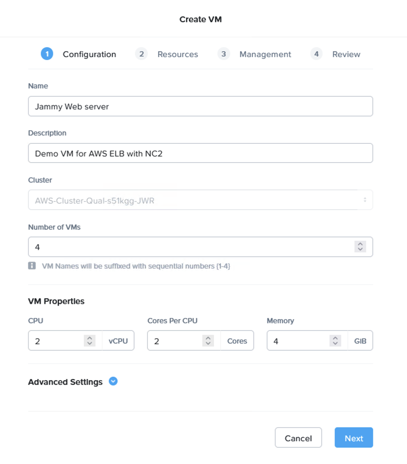
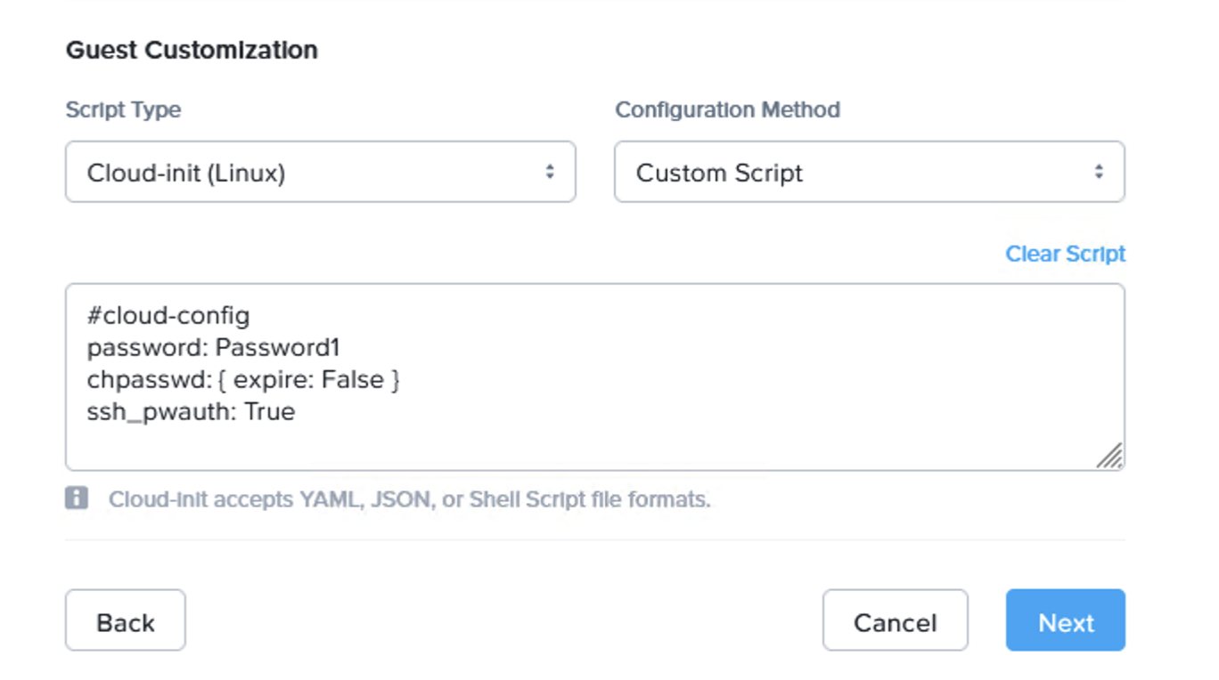
We first deploy a few test web servers. In this case the wonderfully named Jammy Jellyfish edition of Ubuntu Server as a cloud image. Feel free to download the image from here:
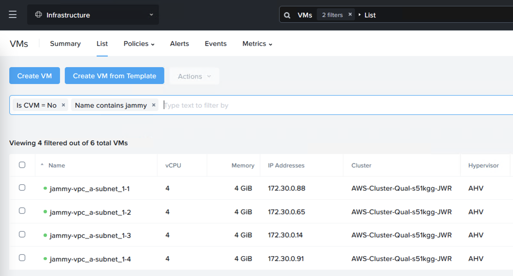
Now we have our VMs ready. I’ve installed the Apache web server to serve pages (apt install apache2) but feel free to use whatever works best in your setup.
I used the following index.html code to show the server ID
Configure floating IP addresses for the web servers
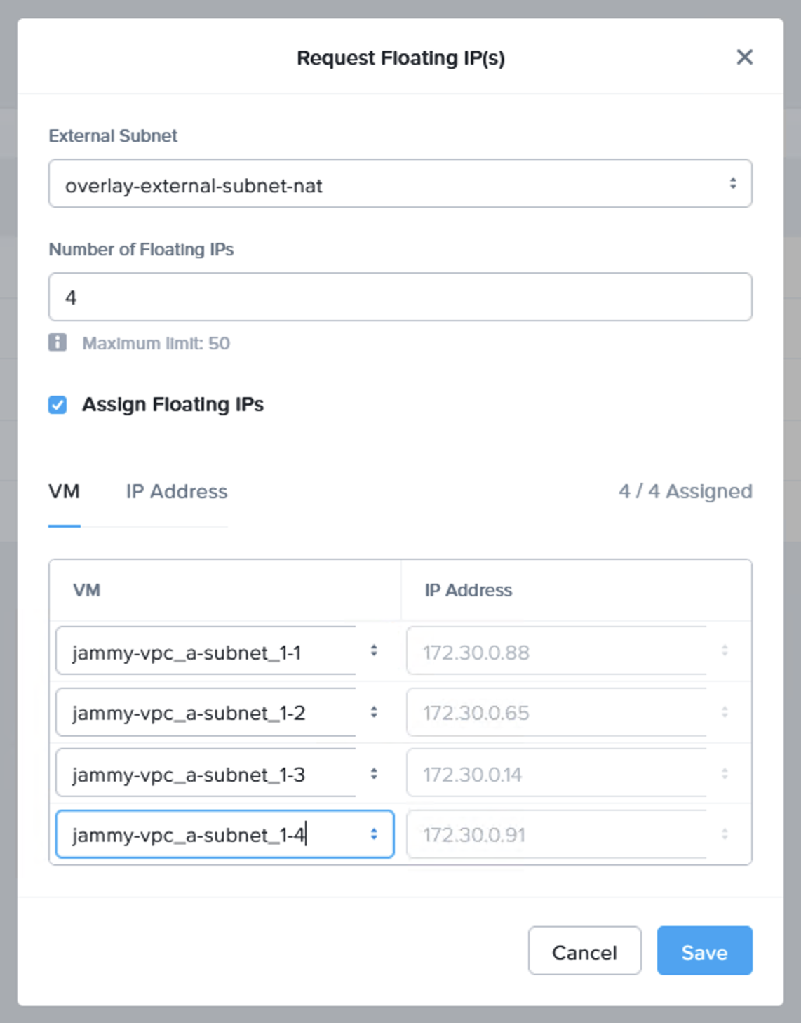
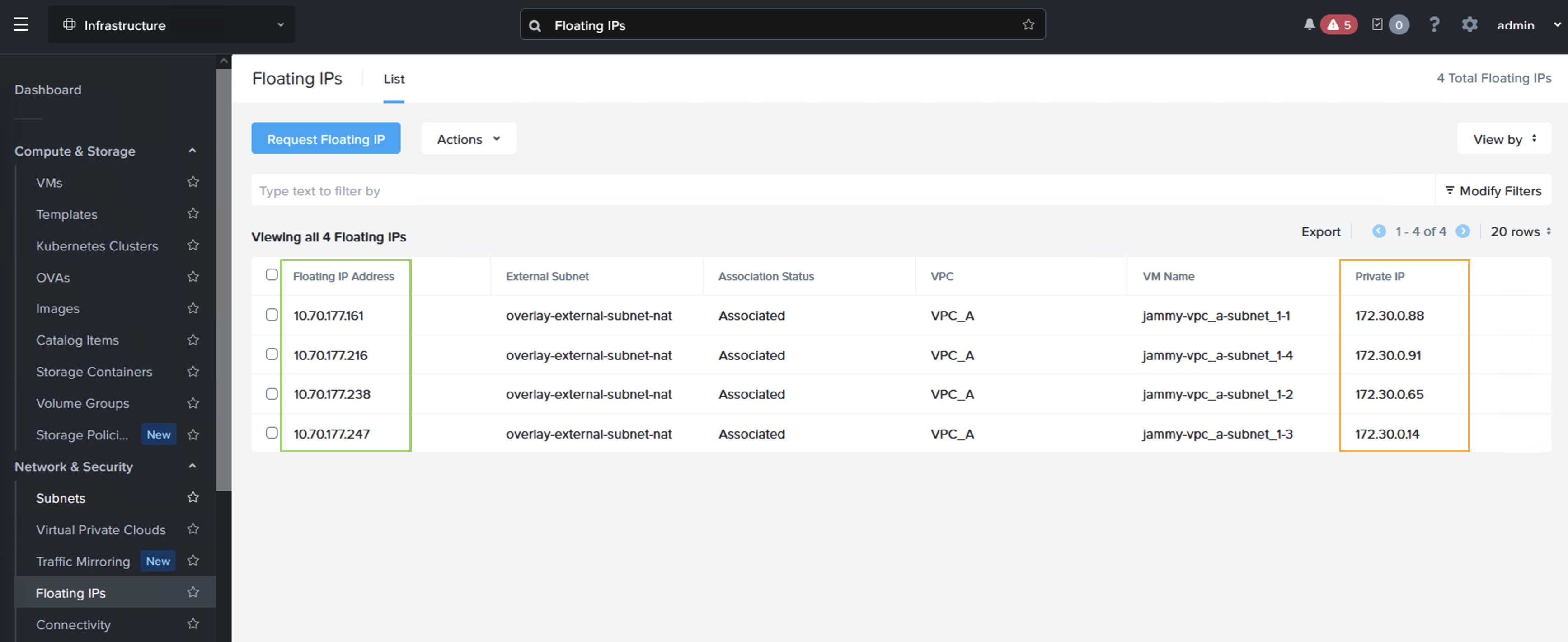
Next we request a few floating IP addresses from the VPC which NC2 is deployed into and then assign one IP each to our web servers. Luckily Prism Central makes also this very easy to do – in a single step! From “Compute & Storage”, select “Floating IPs” under “Network & Security”:
After assigning the IPs we can see that each VM have both an internal and an external IP address, where the “external” IP comes from the AWS VPC CIDR range
Creating an AWS LB target group
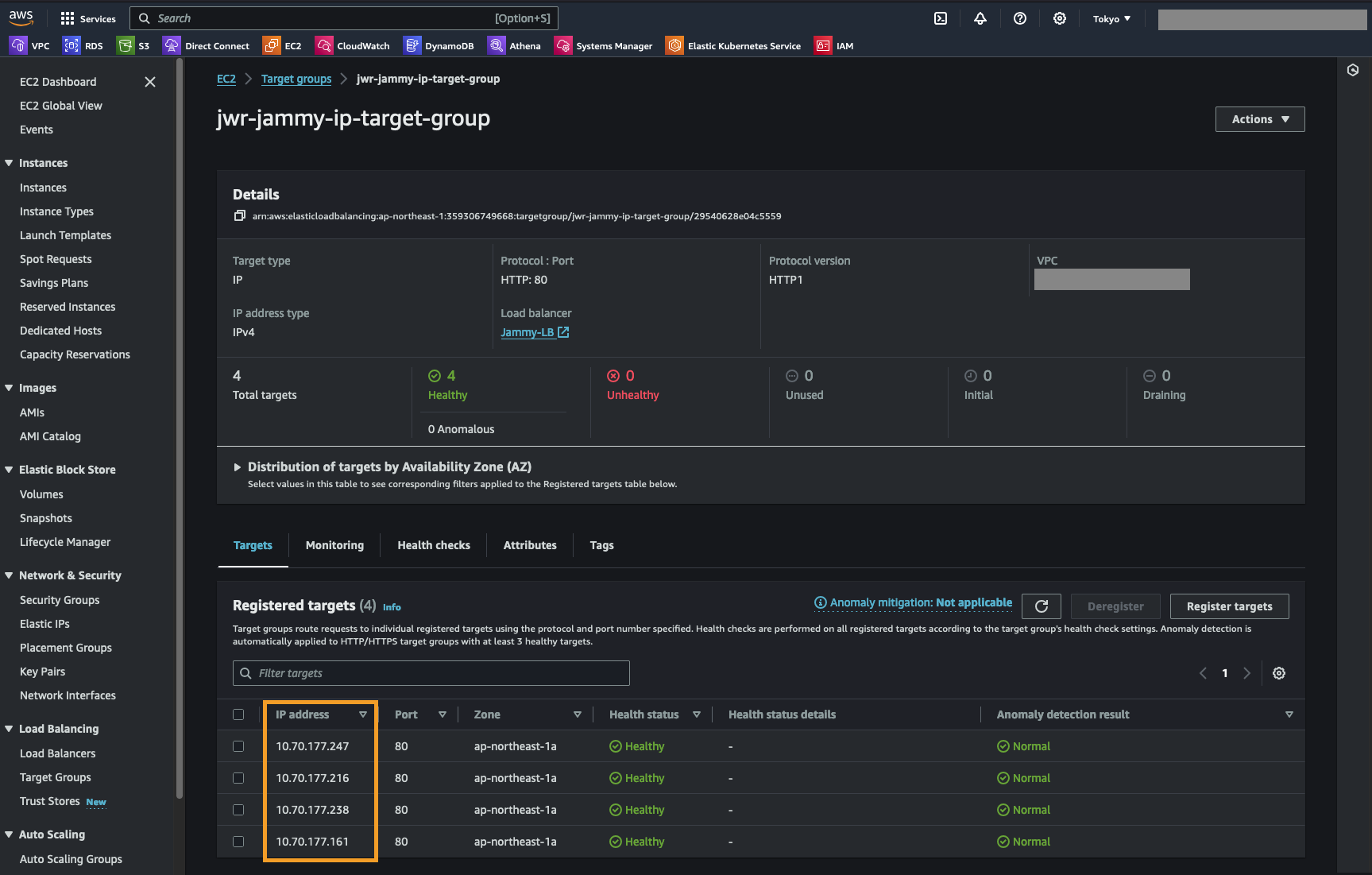
Next we create a target group for the AWS ALB which we deploy in the next step. The LB target group simply contain the Floating IP addresses we just assigned as well as a health check for the web root of these web servers.
We create an “IP address” target group and set the health check to be HTTP, port 80 and the path as “/” or the web root.
We then add the Floating IP addresses we created previously
Create the Application Load Balancer (ALB)
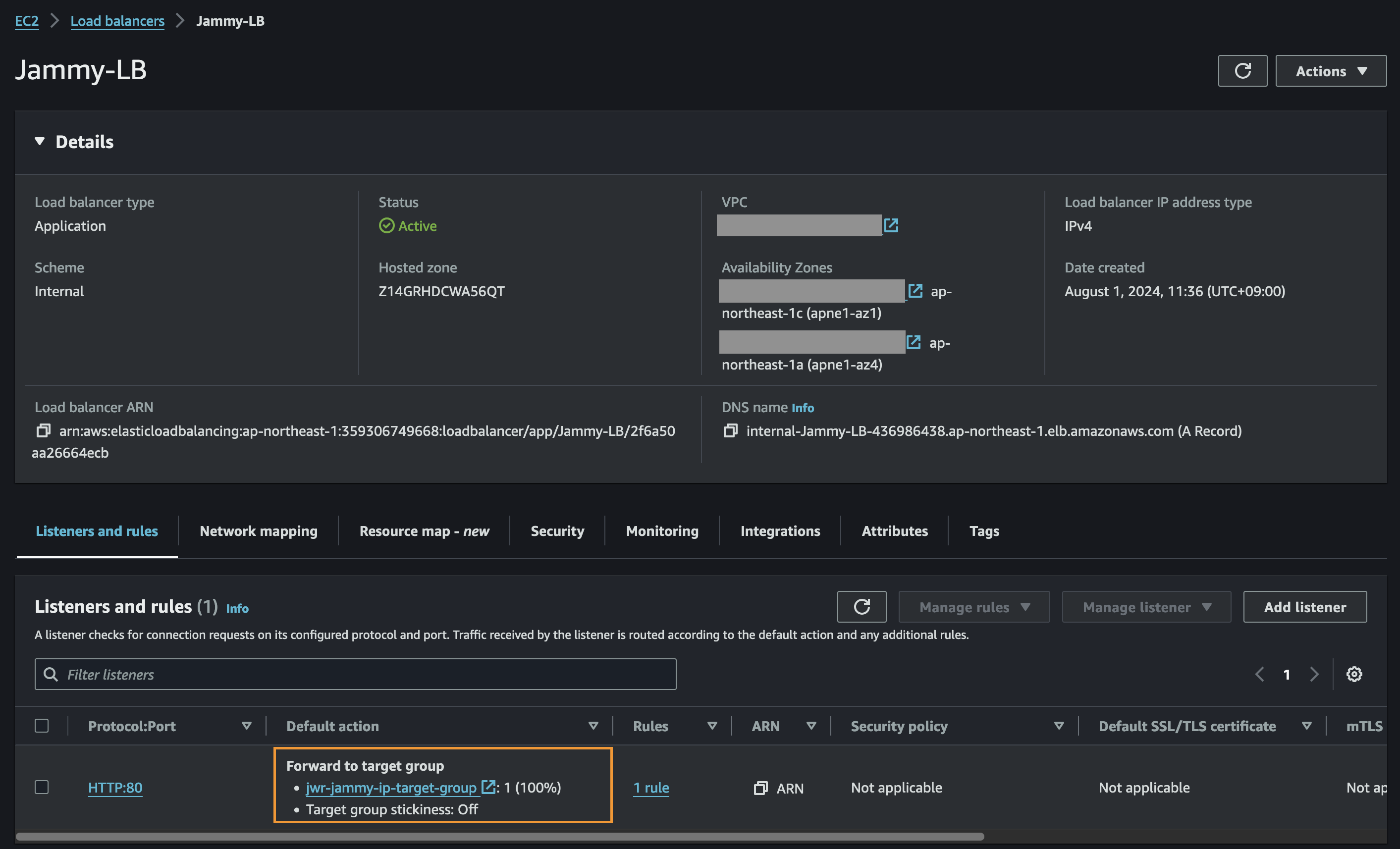
Finally we create the ALB and assign it to our target group
Test of the ALB
Now we’re all done and can access our ALB to see if it shows balances between the NC2 VMs as expected.
We’re getting a different web server each time we refresh the page – all good!
That’s all for now. Hope that was helpful and thank you for reading!
For infrequent VPN connectivity between on-prem labs / data centers and AWS it doesn’t make sense to have a permanent VPN connection up 24/7. However, configuring the on-premises Mikrotik router each time is time consuming and error-prone when done manually.
Functionality
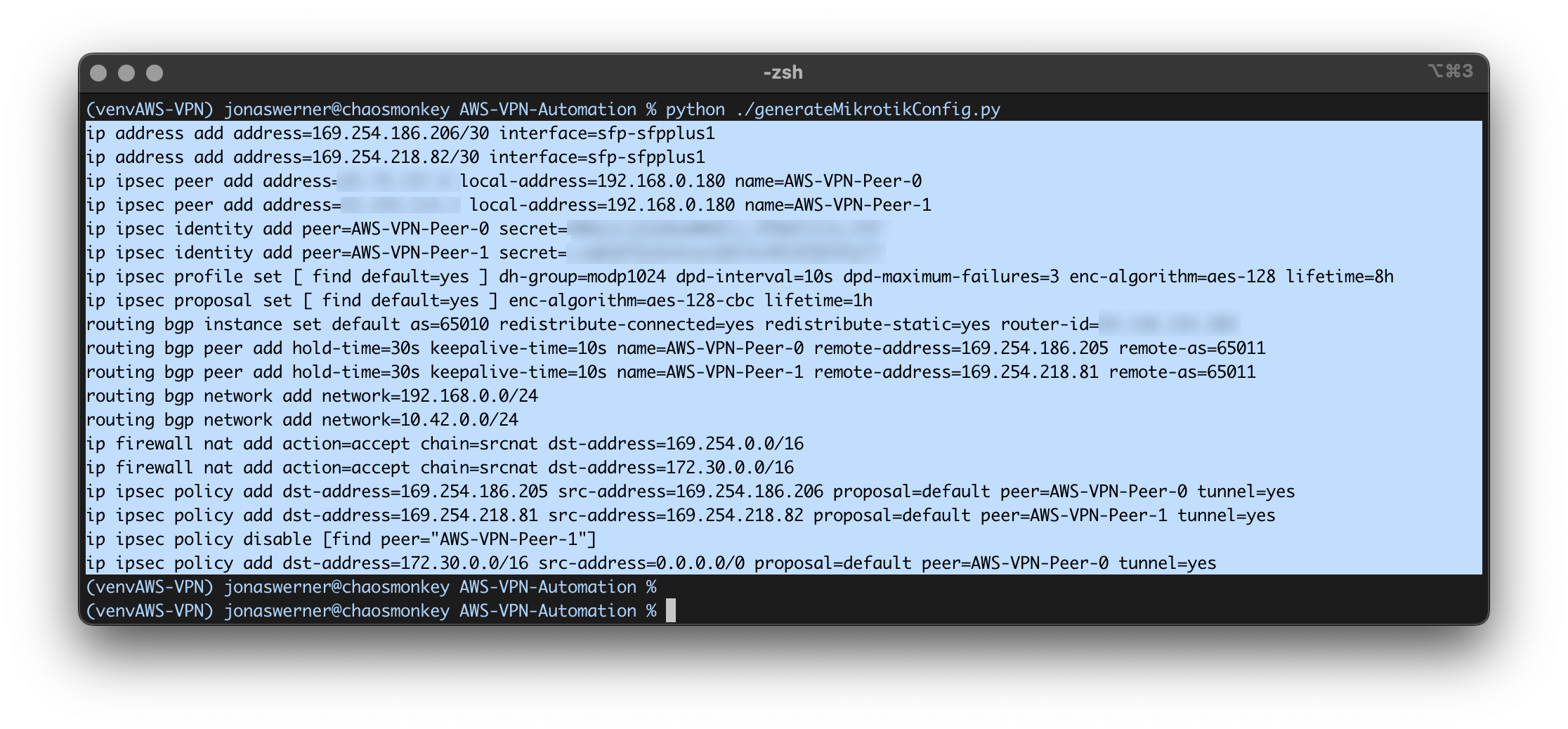
This Python script connects to AWS using boto3, reads the details for the first VPN connection it can find and then generates the commands required to set up:
Inside IP addresses for the VPN tunnel
IPsec proposal settings
IPset profile settings
IPsec peers
IPsec secrets
BGP peers
BGP networks to advertise
Firewall setting
etc.
After the commands are generated, simply copy and paste into a Mikrotik CLI window over SSH or similar and the connection will come up in a couple of minutes.
Prerequisites
This script only handles the on-prem side of the connectivity. It assumes the following is already in place at the AWS side:
VPC with subnets
CGW (Customer Gateway)
VGW (Virtual Private Gateway) which is attached to the VPC
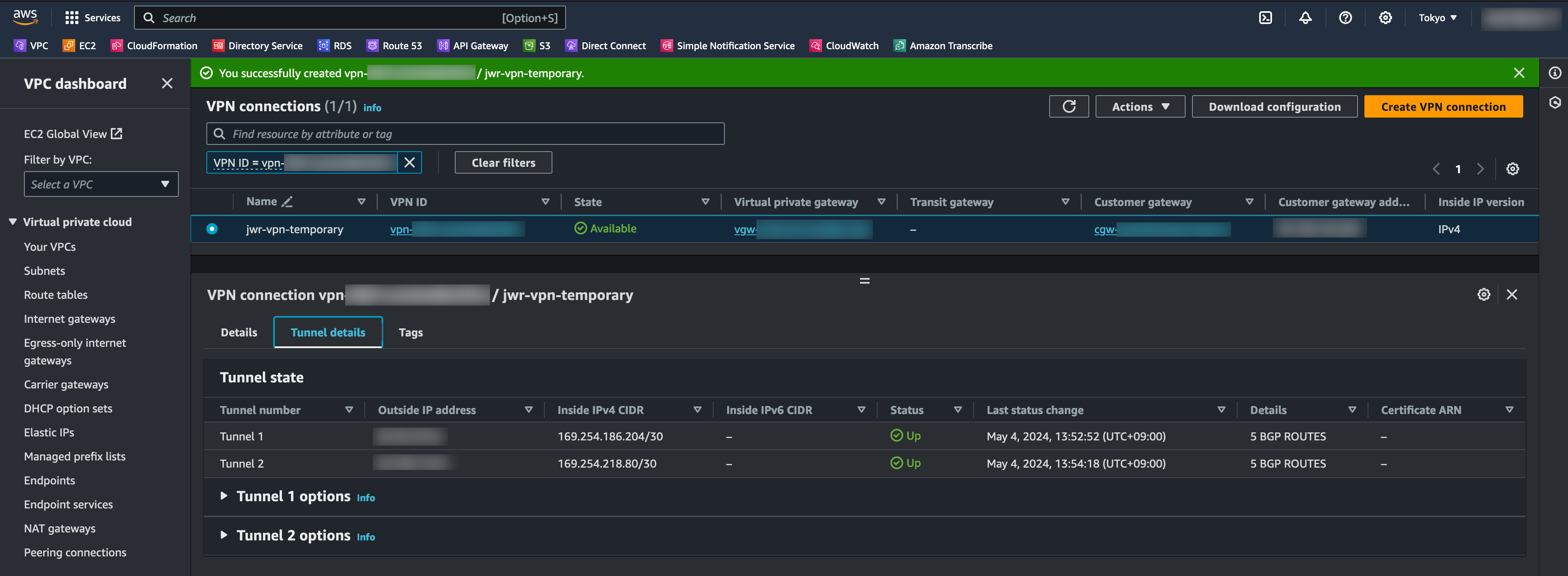
The AWS side has been configured but IPSEC and BGP are both down
Running the script generates the commands required to connect the Mikrotik to AWS
Copy and paste the generated commands into the Mikrotik CLI
After a couple of minutes, IPSEC is up and routes are dynamically shared over BGP
More information
For more information, including how to set up the AWS VPN configuration and a more detailed explanation of the manual steps to configure the Mikrotik router, please refer to this blog post: https://jonamiki.com/2022/05/04/mikrotik-vpn-to-aws-vpc/
Did you ever wish you could host your own multi-player gaming servers with k8s? In that case I have great news, because in this post we’re covering how to deploy online multi-player game server containers with EKS Anywhere on Nutanix infrastructure.
Components
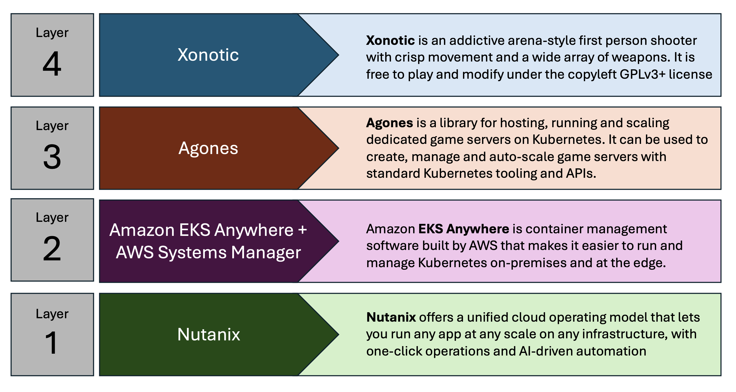
The game in question is Xonotic, which is a classic, fast-paced, multi-player shooting game based on the Quake engine. To deploy it we use Agones – a platform for running, scaling and orchestrate multi-player gaming containers on k8s.
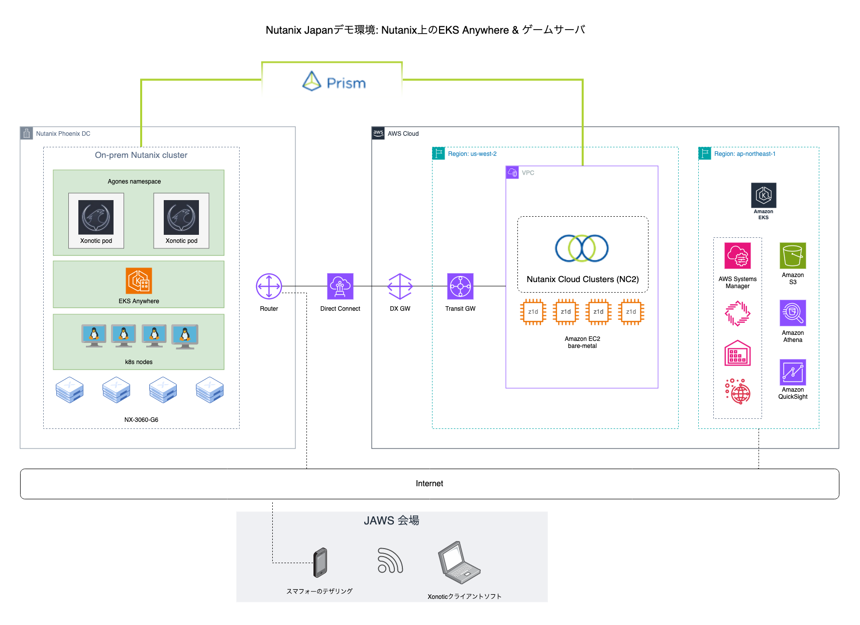
Agones, in turn, goes on top of EKS Anywhere which runs on a Nutanix cluster. In this case we have deployed a cluster in our Phoenix DC, which is also linked with a Nutanix NC2 cluster on AWS.
Nutanix clusters on-prem in Phoenix and in AWS are managed holistically through the Nutanix Prism Central management console. K8s management is done by registering the EKS Anywhere with the EKS service in AWS. K8s node management is done through SSM or Amazon Systems Manager.
Architecture
The two Nutanix clusters (on-prem and cloud) are linked via a Direct Connect line and can be managed holistically using private networking.
The gaming components are managed through standard the k8s toolset while EKS in the AWS console is used for monitoring of the cluster.
The k8s nodes run as virtual machines on Nutanix and each have the SSM (AWS Systems Manager) agent installed. This makes it possible to monitor the VMs, do patch management and even remote connectivity through the AWS console
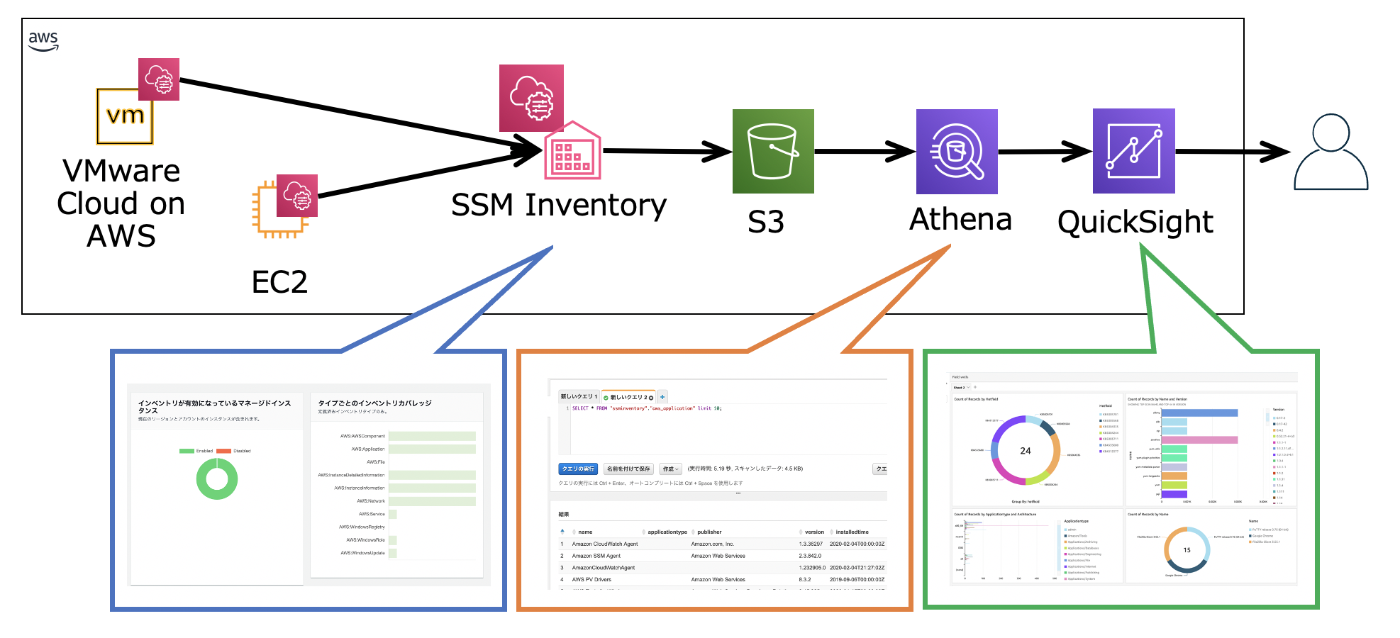
Disclaimer: Inventory data from SSM can be sent to an S3 bucket, converted with Athena and then displayed in graphical form through Amazon Quicksight, as is shown to the right in the diagram. This guide doesn’t go through those particular steps, but they are well documented on the Amazon website.
Overview of the architecture both on-prem and in the cloud. Pardon the Japanese script here and there -this was created for a Japanese event after all
The EKS management and SSM connectivity is done to public AWS endpoints in this case, so it goes over the internet. It would also have been possible to do this over private networking through the DX connection, but I don’t have the IAM privileges to create anything new in the account NC2 is running in.
Overview of steps
The following steps will be covered while building the environment
Step
Goal
Task
1
Holistic Nutanix cluster management
Prism Central download and configuration
2
Building EKS Anywhere node image #1
Download and deploy Ubuntu 22.04 image
3
Building EKS Anywhere node image #2
Create VM and follow image-builder steps
4
EKS Anywhere deployment
Run EKS Anywhere installer from Ubuntu
5
k8s cluster management
Register EKS Anywhere with AWS
6
k8s node management
Install SSM agent on EKS Anywhere nodes
7
Game platform orchestration
Installation of Agones platform
8
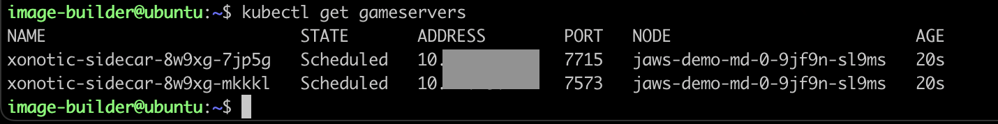
Game server deployment
Creation of Xonotic pods through Agones
9
Good-old fun!
Install the Xonotic client and go fragging!
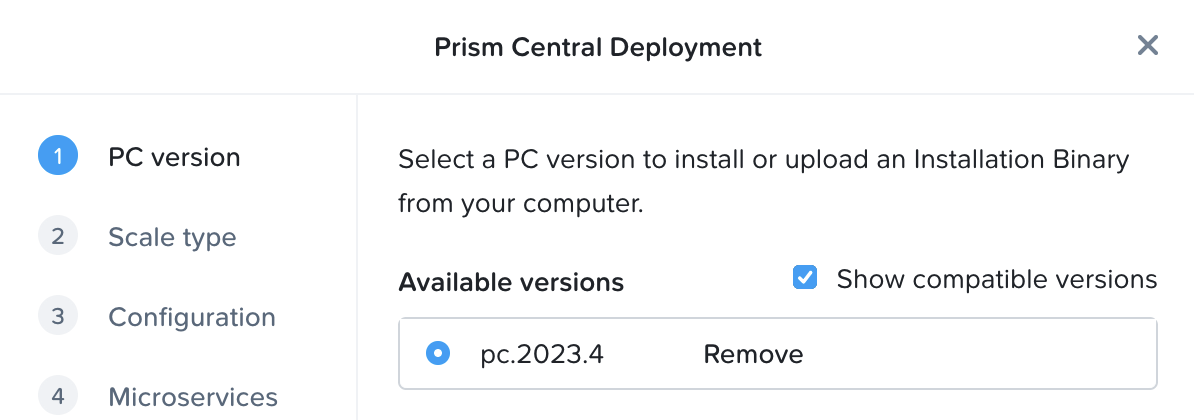
Step 1: Prism Central download and configuration
If not yet deployed, download and deploy Prism Central through the Prism Element UI as per the below.
Once Prism Central has been deployed, reset the admin password over the CLI. SSH to the Prism Central IP using the user “nutanix” and the password “nutanix/4u”. Reset the password using:
ncli user reset-password user-name=admin password=yourpassword
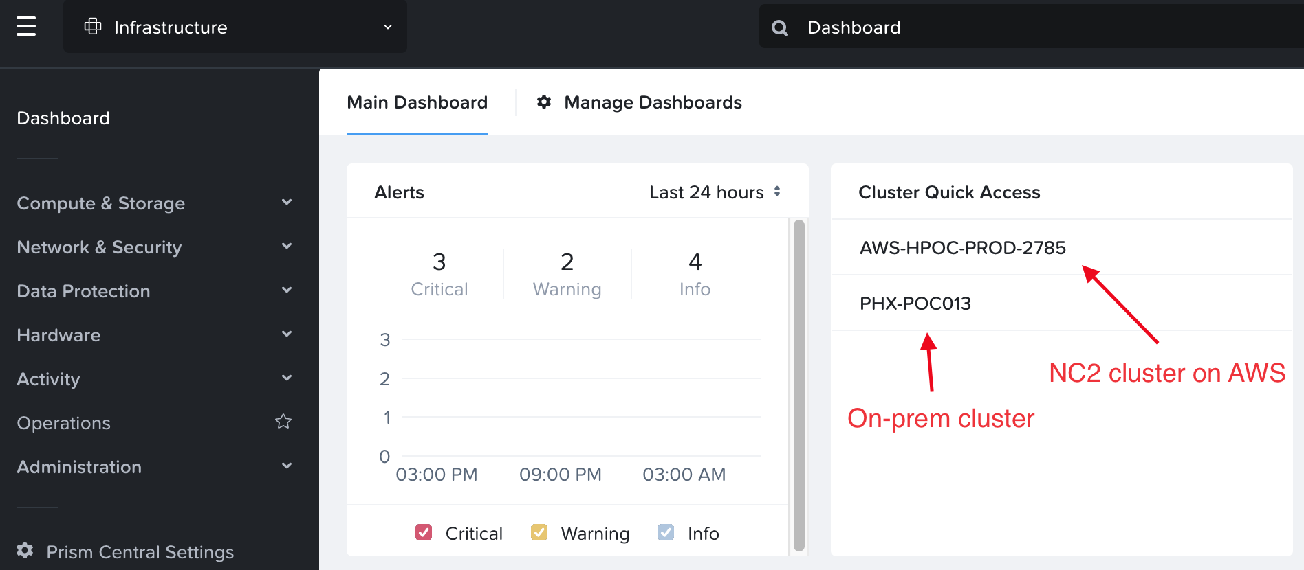
On each cluster, register with Prism Central through the Prism Element UI. Once registered, the clusters show up in Prism Central as per the below
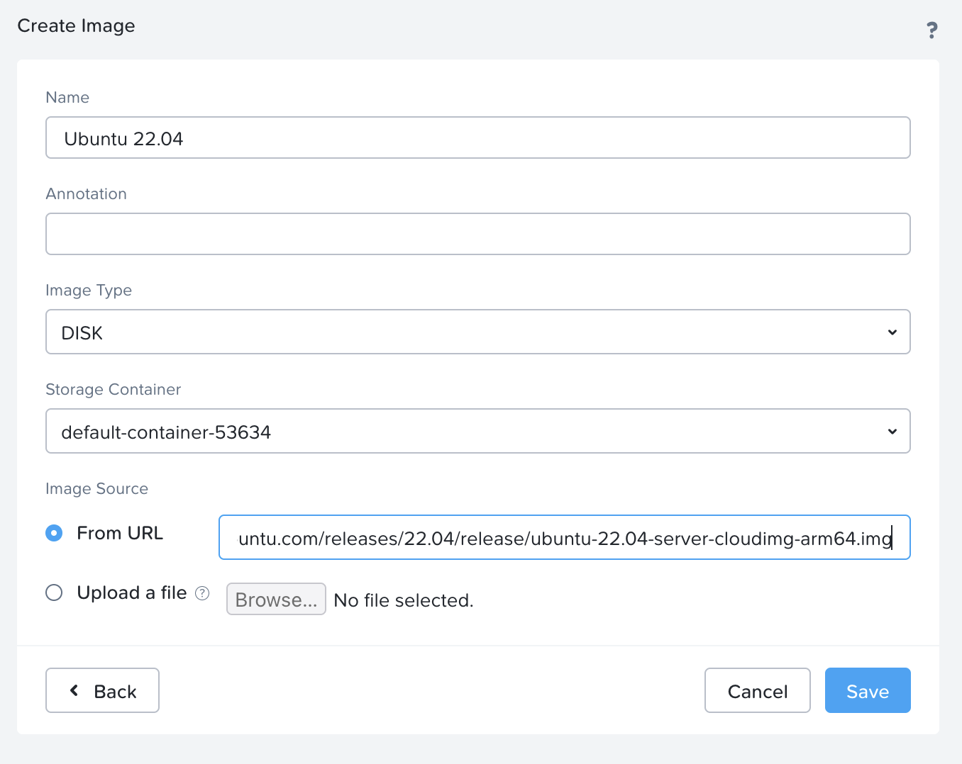
Step 2: Download and deploy Ubuntu 22.04 image
From the Ubuntu website, copy the URL to the Ubuntu image (Jammy Jellyfish) from here:
Be sure to pick the ubuntu-22.04-server-cloudimg-amd64.img and not the disk-kvm image as the kvm image won’t boot.
Add it as a DISK image from URL in the Nutanix web UI:
Step 3: Create VM and follow image-builder steps
Use the image to create a new Ubuntu VM.
I used 2 CPUs with 2 cores each and 8 Gb of RAM.
Delete the CD-ROM drive
Add a NIC.
Set the disk to clone from the image created above
Set boot mode to UEFI rather than the default BIOS.
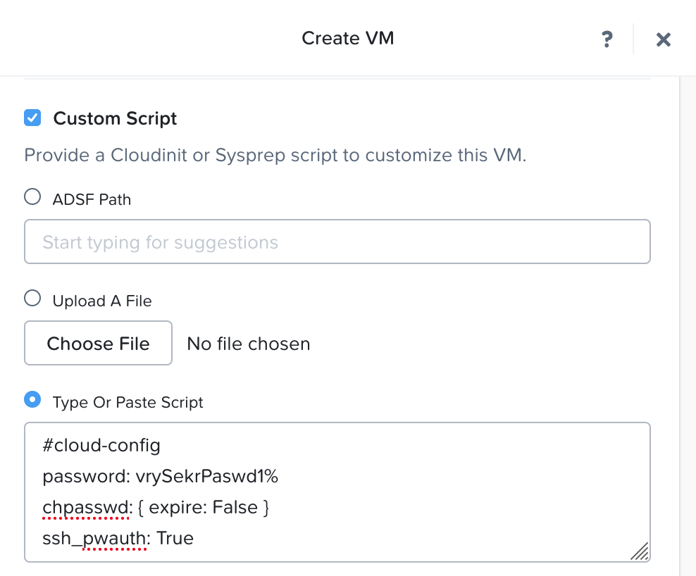
When given the option to add a Custom Script, add a cloud init snippet as per the below to enable SSH (with password rather than key) and set your password
Disk update: You’ll note that the disk created from the image is very small – just 2.2 Gb. Changing the disk size during VM creation isn’t supported, but it can be made larger afterwards. Just accept the size for now and update the disk size once the VM shows up in the inventory. I set mine to 50 Gb.
Don’t start the VM just yet. First we want to add a serial port to the VM through the Nutanix CLI. SSH to any CVM in the cluster and issue the below command:
Now we can power on the VM and log in over SSH using the password set through the cloud init script.
For the image creation, there are official instructions from AWS here. However, I found that some of the official steps needed to be modified to work. Please refer to the below if you want to do the same as I used when creating the image:
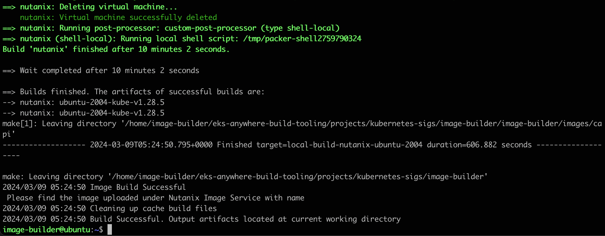
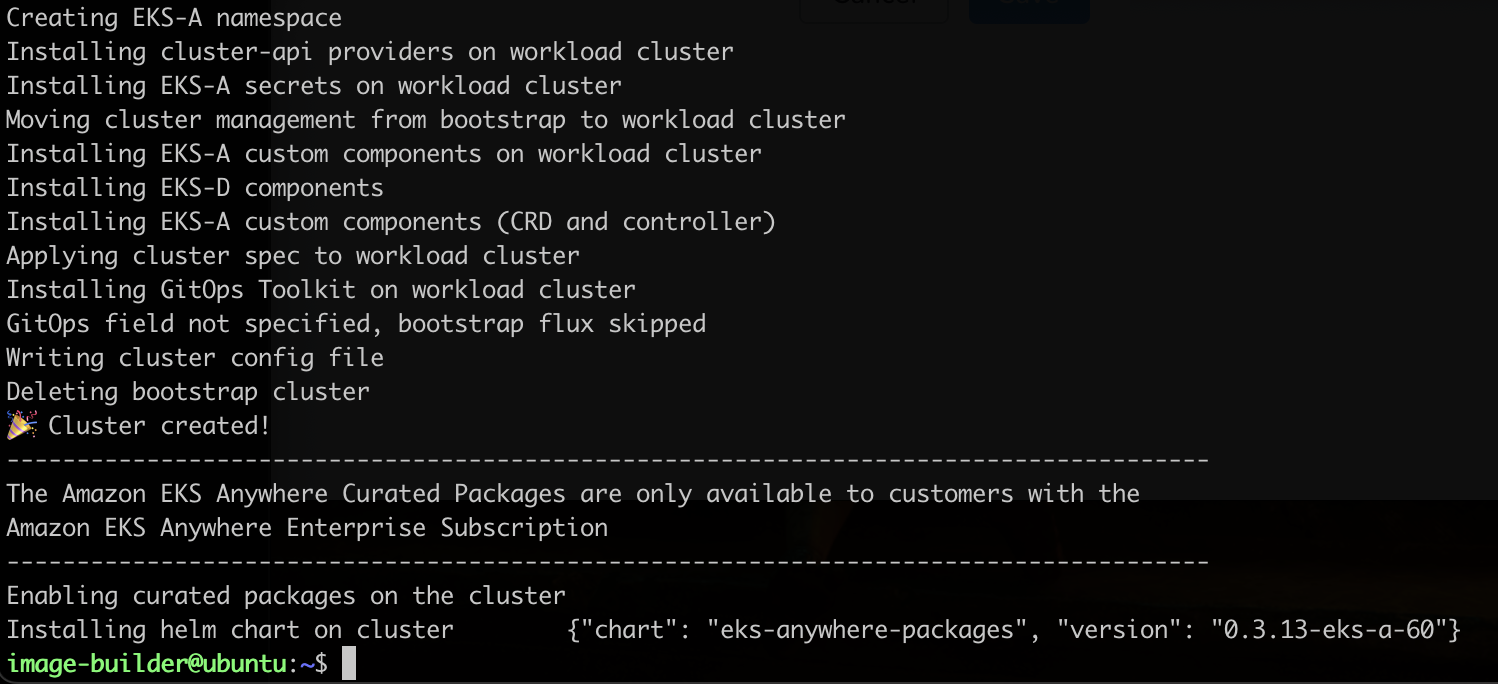
Now we are ready to execute image-builder and create the image. In this case we create an image for version 1.28. This will take around 10 minutes to complete
Once complete you should be greeted with the following message:
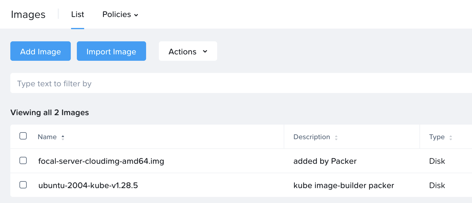
In the list of images in Prism, the new k8s image will show up as follows
Step 4: EKS Anywhere deployment
Now we have an image and are ready to start deploying EKS Anywhere …. well, almost. First we create a configuration file which then is used as the template for the deployment.
Edit the cluster-config.yaml file to adjust to your local environment
Update the cluster-config.yaml file created in the previous step to point to the Prism Central environment you’d like to use. For a lab environment you may also want to disable TLS certificate check. Official instructions for how to modify the file are listed here.
The entire file is too long to upload here, but the fields I’ve modified are:
Key
Value
controlPlaneConfiguration.count
3
controlPlaneConfiguration.endpoint.host
Floating IP to use for control plane VM
kubernetesVersion
1.28 (to match with the image built)
workerNodeGroupConfigurations.count
3
spec.endpoint
Prism Central IP / FQDN
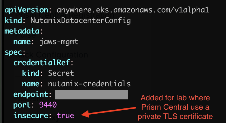
spec.insecure
true (spec.insecure is a new entry)
spec.cluster.name
Prism Element cluster name
spec.image.name
Name of k8s image created earlier
spec.subnet.name
Name of subnet to use for k8s nodes
spec.users.name.sshAuthorizedKeys
Copy and paste your RSA SSH key here
Quick screenshot showcasing the addition of the “spec.insecure” parameter for lab clusters without a valid SSH/TLS cert:
Deploying the cluster
First export the credentials to Prism Central as per the below:
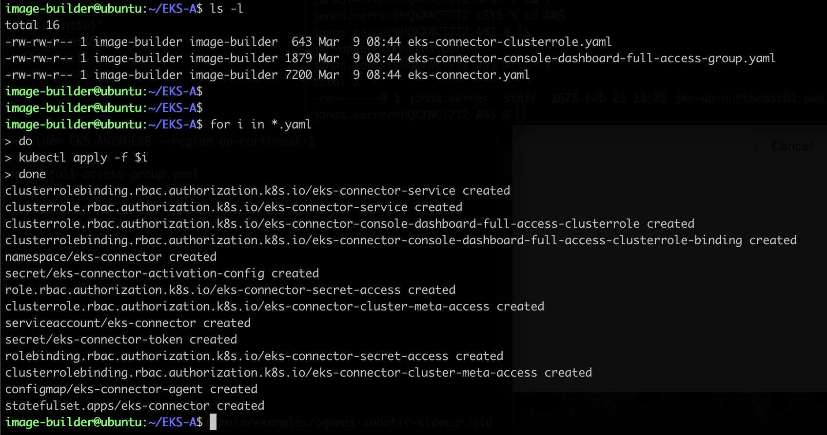
image-builder@ubuntu:~/EKS-A$ ls -1
eks-connector-clusterrole.yaml
eks-connector-console-dashboard-full-access-group.yaml
eks-connector.yaml
image-builder@ubuntu:~/EKS-A$
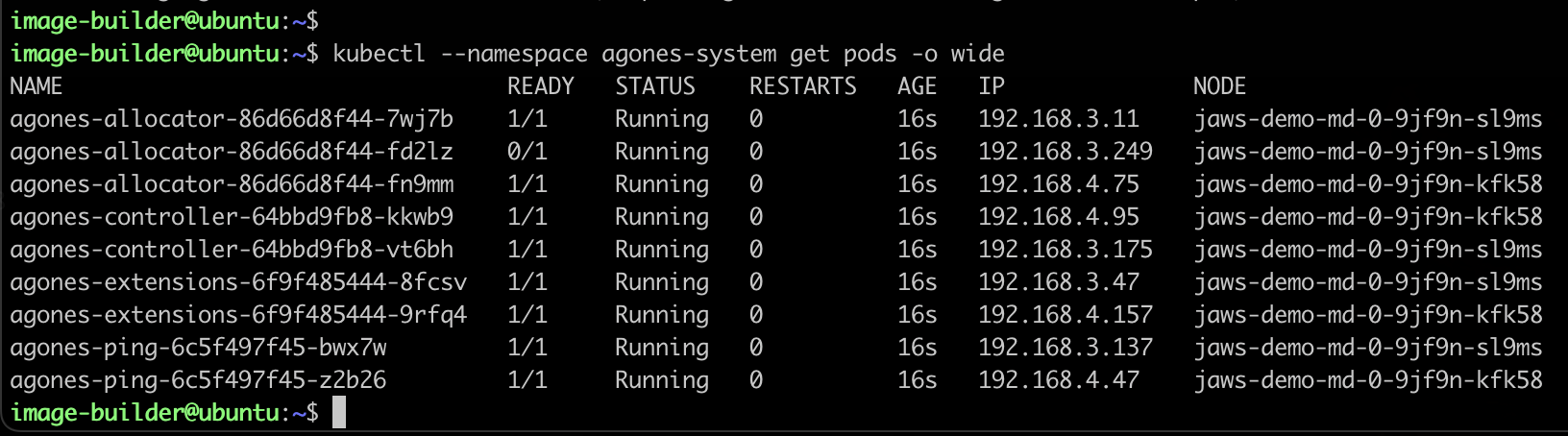
Then apply the configuration files with kubectl
kubectl apply -f CONFIG-FILE
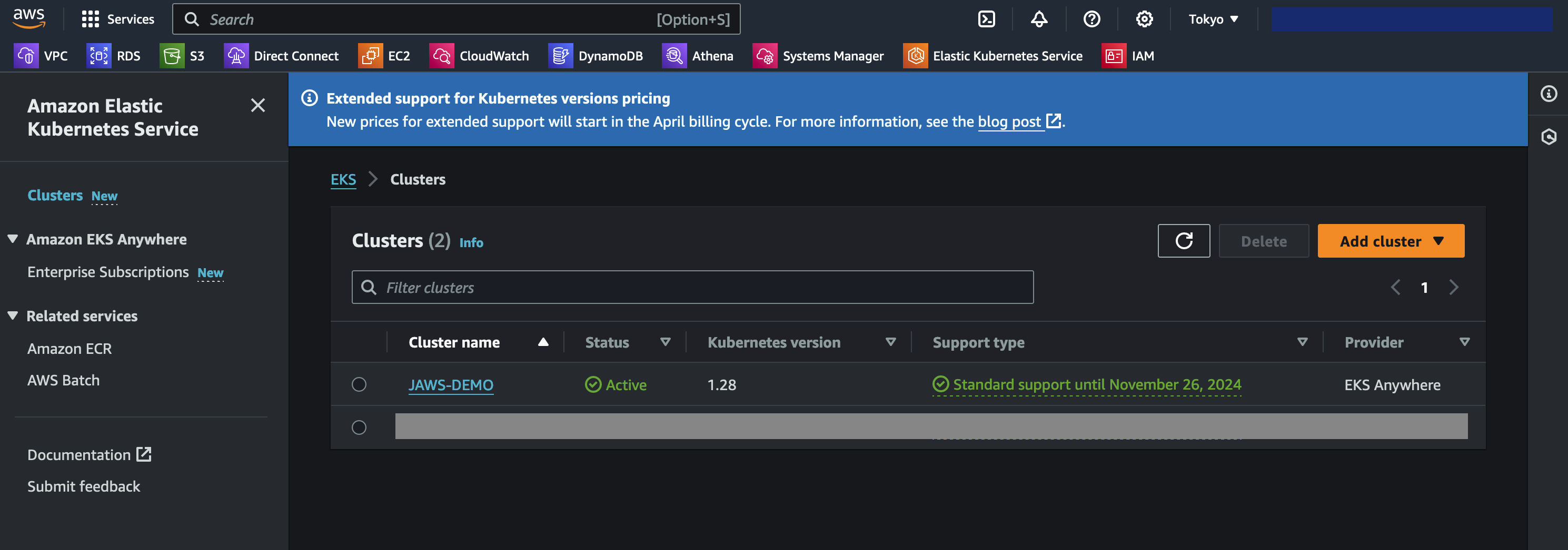
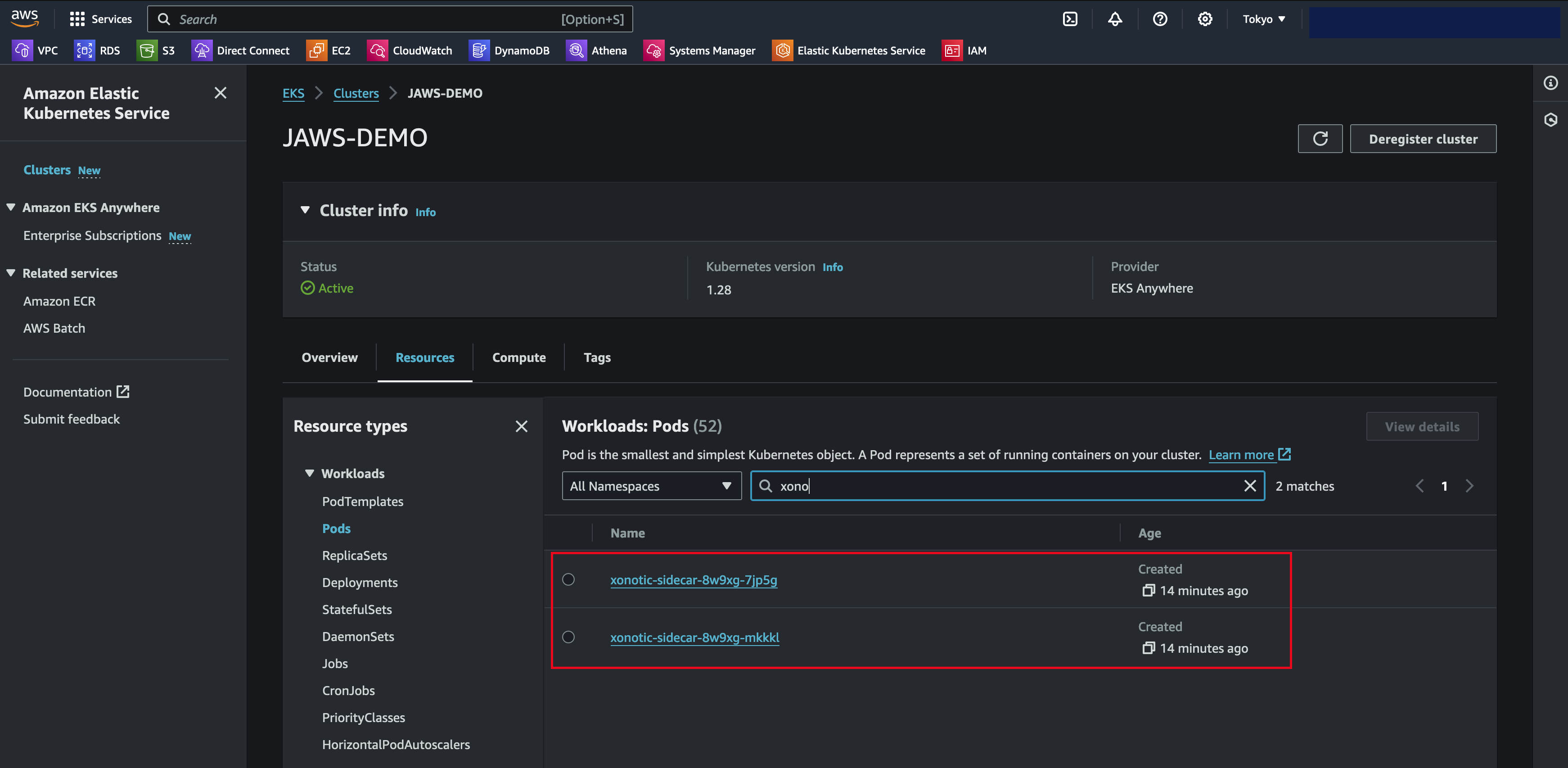
Access the AWS console, navigate to Amazon Elastic Kubernetes Service and verify that the cluster shows up as it should. Ensure you are in the region you selected when generating the yaml config files
Click the cluster name , go to the Resources tab and select Pods. Here you filter to find the Xonotic game pods as per the below
Step 6: Install SSM agent on EKS Anywhere nodes
With the AWS Systems Manager agent installed, it is possible to monitor the k8s cluster nodes, get their software inventory, do patch management, remote access and various other things
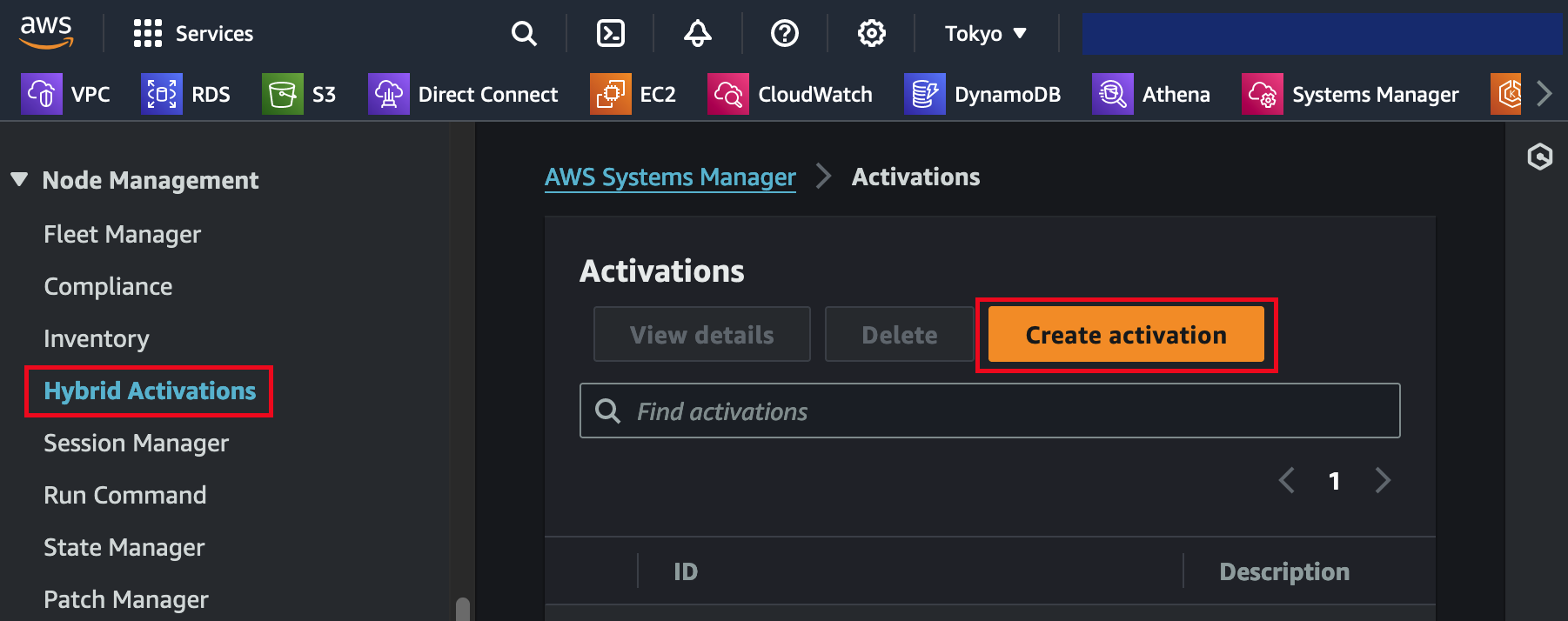
The first thing we do is to create a managed node activation in the AWS Console. Navigate to Systems Manager and select Hybrid Activations. Be sure to pick the right region.
Save the resulting activation details as they are used when registering installing the SSM agent and registering the the k8s nodes
For the agent installation and registration, please follow the official guide here:
Mac users on Apple silicon can install the client with Brew
brew install xonotic
Start the client, select multi-player and add the IP and port of your game server
Play the game!
Closing
This has been a somewhat lengthy guide on configuring k8s on top of Nutanix with the intent of running containerized game servers. Hopefully it has been informative. Originally I wanted to expand the section on SSM and other features on managing the cluster through AWS but thought this blog post was long enough already. Perhaps those areas will be worth re-visiting later on if there’s interest.
VMware Cloud on AWS is configured to be highly secure from the get-go. However, there are additional add-on services both on the VMware Cloud on AWS side and the AWS native service side which can be of benefit for those looking to add additional layers of security to their cloud environments. This guide aims to provide an overview of those services as well as list links for further reading
Overview
Maintaining tight access control for workloads and ensuring they are on the latest patch revisions is central to running an efficient and secure IT environment. In this post we cover how to heighten security by leveraging the tools which comes with AWS Systems Manager and complementing AWS native services. This way IT administrators will be empowered with tools central to their quest of reaching higher security levels while simultaneously being able to reduce management overhead.
Defining good security practices
While security in both on-premises and cloud environments is a broad topic, there are a few security practices which generally makes good sense to implement regardless of where workloads reside. In this section we will cover a few points to define good security practices and in the latter half we will look at what tools can be leveraged to implement this in practice.
Restricting access
Adhering to the principle of least privilege by assigning access to workloads only to those who actually need to administer those workloads. It is easy to assign a single or a few administrative accounts with blanket access across all virtual machines in a VMware environment but it’s certainly not best practice. We will look at tools to help divide and limit access as required in this document.
Tracking access
After limiting access to those who require it for their respective roles it also makes sense to track who has accessed what virtual machine at what time and to centralize the logging of workload access. This makes it easier to back track in case of either a security breach or purely for troubleshooting purposes.
Limiting the attack surface
Virtual machines are generally accessed by administrators over RDP for Windows or SSH for Linux. These protocols are frequently the first ones that hackers will try to exploit. Normally closing these access ports would make managing the workloads remotely a challenge, if not impossible but when using AWS native services in conjunction with VMware Cloud on AWS the methods and options for secure remote systems management increase. For this we leverage AWS Systems Manager in combination with VMware Cloud on AWS.
Having insight into what software is installed where
While keeping operating systems patched and up to date help safeguard against known Common Vulnerabilities and Exposures (CVEs), old or non-approved software can also provide attackers with additional vectors through which to gain access to otherwise protected systems. Gaining clear insight into what is installed and what versions are running in an environment is usually a priority for the security minded IT administrator. Here AWS Systems Manager can be a powerful ally as it integrates well with the virtual machines running on top of VMware Cloud on AWS.
Addressing CVEs quickly
New bugs are found frequently and as they are made public they usually end up in the CVE database. Patching these security holes is of course vital in maintaining a secure environment. Likewise is scanning for attempts to exploit these vulnerabilities with an IDS / IPS system. VMware Cloud on AWS add-ons can be leveraged to assist with this.
Alerting when something happens
Hackers will often spend a significant time in a compromised environment while they investigate ways to broaden their attack by mapping out the network and additional systems to target. These days, assuming that an attack will succeed at some point is common. Instead of just hardening the external-facing systems the internal systems should get a similar treatment. Equally important is to get alerted at an early stage to limit any potential blast radius after a system has been compromised.
Centralized logging
The first indication that intrusion attempts are being made can often be found in the log files of the systems being accessed. Having single source of truth into which all logs and access attempts are sent is vital when it comes to maintaining a birds-eye-view of an environment. It also makes it a lot easier if data doesn’t have to be correlated across multiple locations and tools.
Ensuring firewalls are configured correctly and notify / revert if this changes
A properly configured firewall can make the difference between a secure system and one which can easily be hacked. The old “hard shell – soft core” approach is no longer relevant in today’s environments when everything is connected and therefore potentially an access vector for an aggressor. Keeping standards for firewall configurations and ensuring they are properly applied on an ongoing basis is a great help in making sure that internal as well as external systems are properly protected against attack.
Get notified and react quickly if a hackers gain a foothold in your environment (IDS / IPS)
It’s not a question of “if” but “when” an attack succeeds. Once an assailant has gained a foothold they are inside your environment. The next step is to scan and map out other vulnerable systems in the vicinity. Quick reaction times can limit or even prevent any further intrusion.
Guard against ransomware by having immutable backups of important data and virtual machines
Hoping for the best and planning for the worst case scenarios involve having backups and a Disaster Recovery (DR) plan for when data has become corrupted and / or encrypted by ransomware. Read more about VMware Cloud on AWS add-ons for DR and how AWS native tools can provide immutable backups of all virtual machines and their data later in this blog post.
Using VMware Cloud on AWS add-ons and AWS native services to enhance security
The above may be good points for enhancing security, but how can they be implemented in a VMware Cloud on AWS environment? The following three sections show how to do so in more practical detail:
Leveraging AWS Systems Manager (SSM)
Leveraging VMware Cloud on AWS add-ons
Leveraging additional AWS native services
1. Leveraging AWS Systems Manager
AWS Systems Manager involves several services which in combination provide powerful management capabilities.
For Restricting access and Limiting the attack surface it is possible to use AWS SSM Session Manager for remote access rather than connecting to virtual machines over RDP or SSH. Thereby commonly used ports such as 3389 (RDP) and 22 (SSH) can be closed and will therefore significantly reduce the attack surface of the virtual machines.
Additionally, in many cases it is possible to avoid accessing virtual machines directly. AWS SSM Fleet Manager provides a convenient way of connecting to virtual machines by offering access to Windows registry, Windows logs, Windows file system as well as command line access to Windows PowerShell – all through the AWS Console. Graphical desktop access is of course also possible and can be done by forwarding the RDP port of the virtual machine to the local IT admins computer. For Linux machines the access can be had in the same way and a connection to the Linux shell prompt is readily available through the AWS Console.
For Addressing CVEs quickly AWS Systems Manager offers Patch Manager – a centralized way to ensure VMware Cloud on AWS virtual machines and EC2 instances have their latest security patches applied. Create patch baselines, set maintenance windows and tag virtual machines into groups to ensure continuous uptime while patching takes place.
When it comes to gaining Insight into what software is installed AWS SSM has us covered through AWS Systems Manager Inventory. The AWS SSM agent automatically pulls software inventory from managed instances, like VMware Cloud on AWS virtual machines, and displays it through the AWS Console. For even more detailed reports and prettier graphics SSM Inventory can be expanded by putting the inventory data into Amazon S3, query it with Amazon Athena and finally access the query result data from Amazon QuickSight. This way it is possible to generate comprehensive and sometimes even beautiful reports.
2. Leveraging VMware Cloud on AWS add-ons
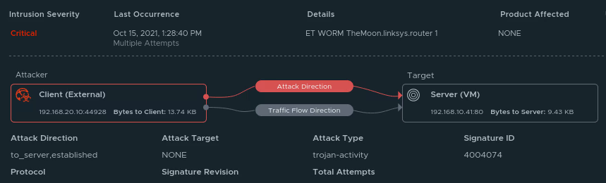
While AWS native services can cover many angles of security and systems management, when it comes to keeping guard inside the VMware Cloud on AWS environment the VMware Cloud on AWS add-on service NSX Advanced Firewall is a powerful solution. NSX Advanced Firewall can be easily be deployed in a VMware Cloud on AWS environment and helps with the security practice of Getting notified and react quickly if a hackers find a foothold in your environment (IDS / IPS). It comes pre-loaded with CVEs to protect against, like SQL injection attacks. However, it can also alert on, and optionally block, both attacks and network scans in real-time.
Disaster recovery is another topic which goes hand-in-hand with good security best practices. Primarily from a standpoint of safeguarding against ransomware. This aligns directly with Guard against ransomware by having immutable backups of important data and virtual machines. For the purposes of DR with VMware Cloud on AWS there are two standout solutions available in VMware Cloud Disaster Recovery (VCDR) and VMware Site Recovery. Both are powerful in their own right and offer recovery from corrupted or encrypted data as well as actual DC disasters of course. Please also refer to AWS Backup in the section below for an AWS alternative to backing up virtual machine data to protect from ransomware and other data loss.
3. Leveraging other AWS native services
A wide variety of AWS native services can be brought to bear to boost security in both a VMware Cloud on AWS or on-premises VMware environment. One aspect is increased insight by centralizing logging and alerting for events and another aspect is backing up data as well as running commands. All these topics are covered in the section below.
CloudWatch and CloudWatch logs
The AWS CloudWatch agent can be installed both in VMware Cloud on AWS and on-premises VMware environments. Instructions for installation are listed here. Once installed, telemetry from virtual machines will be logged in CloudWatch to be used for diagnostics and alerting. Filters can be created where log files are searched for key words and events which can subsequently be used to trigger alerts. Read more about CloudWatch log filtering here: https://docs.aws.amazon.com/AmazonCloudWatch/latest/logs/MonitoringLogData.html
CloudTrail and EventBridge
As covered in the Restricting Access section above, once remote access has been configured to be allowed only through SSM Session Manager, API calls done for virtual machine and instance access can be logged in CloudTrail for later review. This gives a central location for the security team to track who accessed what system at what time. Note that tracking only show when a system was accessed by whom and doesn’t extend to what was done at the OS level. Furthermore, EventBridge can be paired with AWS SNS to generate alerts whenever sessions are initiated, resumed or terminated.
SSM Run Command and AWS Config
When it comes to setting appropriate firewall rules and then ensuring they don’t change unless intended there are two solutions which come in handy. For the AWS native side there is AWS Config with which rules for approved configurations can be set and maintained. For the VMware Cloud on AWS side it is possible to use SSM Run Command to regularly check for and apply firewall settings with PowerShell and Linux shell scripts.
AWS Backup
While the VMware Cloud on AWS add-ons like VCDR and Site Recovery can help with Guard against ransomware by having immutable backups of important data and virtual machines, AWS Backup is a cloud-native option for safeguarding virtual machine data. AWS Backup supports both VMware on-premises and in VMware Cloud on AWS.
When registering a vSphere system with AWS Backup a virtual appliance is downloaded and deployed in the VMware environment. After linking with vCenter it is possible to create backup plans for the VMware environment through the AWS Console. AWS Backup take backups by creating a snapshot of the virtual machine and then backing up the snapshot to AWS. The snapshot is discarded after it has been copied to AWS. Initial backups are full and subsequent backups are incremental.
Conclusion
VMware Cloud on AWS is not a standalone solution but integrates well with a variety of AWS native services. In this blog post AWS Systems Manager and related services were leveraged to enhance security of virtual machines running on VMware Cloud on AWS by centralizing access controls and automating OS patch management.
Maintaining tight access control for workloads and ensuring they are on the latest patch revisions is central to running an efficient and secure IT environment. In this post we cover how to heighten security by leveraging the tools which comes with AWS Systems Manager and complementing AWS native services. This way IT administrators will be empowered with tools central to their quest of reaching higher security levels while simultaneously being able to reduce management overhead
Integrating AWS Systems Manager (SSM) with VMware Cloud on AWS
Deploying SSM can help enhance security for both cloud native and VMware Cloud on AWS environments. This post will show how to integrate SSM with VMware Cloud on AWS for secure remote access as well as security patching of VMs.
Detailed configuration steps are covered below, but the main points are:
Enabling and performing initial SSM configuration
Creating a VPC endpoint for SSM in the VMware Cloud on AWS connected VPC
Creating an inbound endpoint for Route 53
Install the SSM agent and registering the VMs with SSM
The SSM endpoint gives the VMs a private IP to communicate with SSM and the Route 53 inbound endpoint ensures that the VMs receive that private IP when they resolve the SSM FQDN. Without these two endpoints the VMs would communicate with SSM over the internet.
Architecture
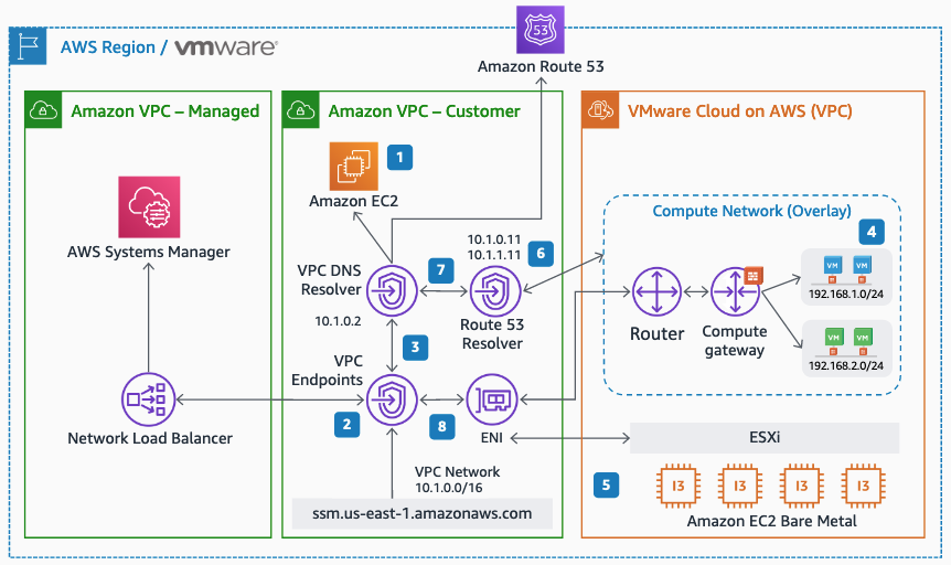
Integrating AWS Systems Manager with VMware Cloud on AWS is relatively straightforward. While AWS SSM comes with public endpoints for VM-to-SSM communication, the preferred way is to use private IP addressing over the connected VPC Elastic Network Interface (ENI). To accomplish this, create an SSM endpoint in the connected VPC and then set the networks on the VMware Cloud on AWS SDDC CGW to use a Route 53 inbound resolver. That way any communication the SSM agent does to the regional SSM endpoint will go over the ENI rather than the internet. No changes on the VMs are required apart from ensuring they use the correct Route 53 DNS resolver.
Overall network architecture for AWS Systems Manager integration with VMware Cloud on AWS
Integrating AWS Systems Manager for the VMware Cloud on AWS environment involves creating an SSM endpoint in the customer connected VPC and adding a DNS inbound endpoint
In this section the practical setup of AWS Systems Manager with VMware Cloud on AWS is covered. General guidelines for getting started with AWS Systems Manager is covered in the SSM User Guide. The steps below are VMware and VMware Cloud on AWS specific and aim to get an environment up and running swiftly.
Overview of steps involved in setting up Systems Manager for use with VMware Cloud on AWS
Setting the systems manager region
Creating an S3 bucket for SSM logs and inventory output
Creating the S3 bucket policy in IAM
Creating the systems manager IAM users
Creating the systems manager VPC endpoints
Creating the R53 DNS inbound endpoint
Pointing CGW DNS to R53
Creating the SDDC firewall rules
Creating a hybrid activation
VM configuration: Installing the SSM agent and registering with SSM
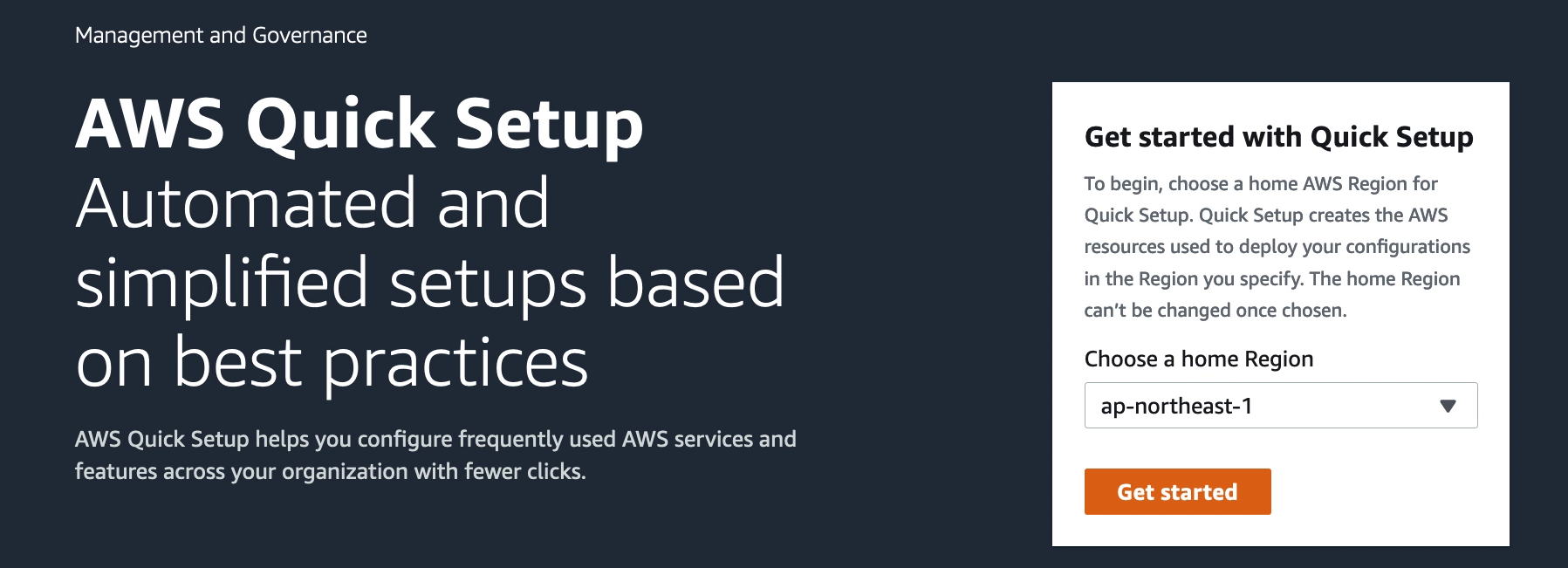
1. Setting the systems manager region and enable Advanced-Tier
AWS Systems Manager is bound to a region of choice when activated the first time. Please pick a region which makes sense to your organization and note that it cannot be changed afterwards. For a VMware Cloud on AWS environment this would usually be the same region as the VMware Cloud on AWS environment is deployed in.
To use advanced features of AWS SSM, like patch management of VMware VMs, Advanced-Tier has to be enabled. This will incur an extra charge for instance management. At the time of writing the daily cost for one instance would be $0.1668 USD. Please refer to the SSM pricing structure for more detail and up-to-date pricing.
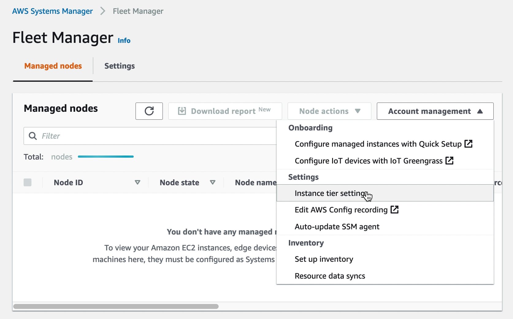
Once AWS SSM has been set to your preferred region, access “Fleet Manager” and under “Account management” select to modify the settings for Instance tiers.
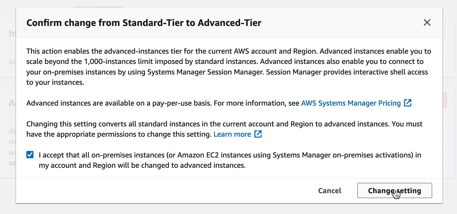
Under the “Instance tier settings” confirm change from Standard-Tier to Advanced-Tier
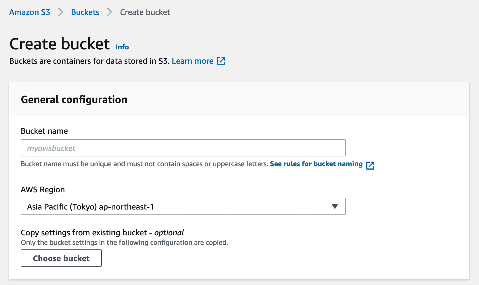
2. Creating an S3 bucket for SSM logs and inventory output
Having a designated S3 bucket for SSM logs and other output, like inventory data, makes administration easier. The output can later be accessed for tracking, troubleshooting or even for access via Athena where inventory data can be formatted using SQL queries and used in QuickSight reports.
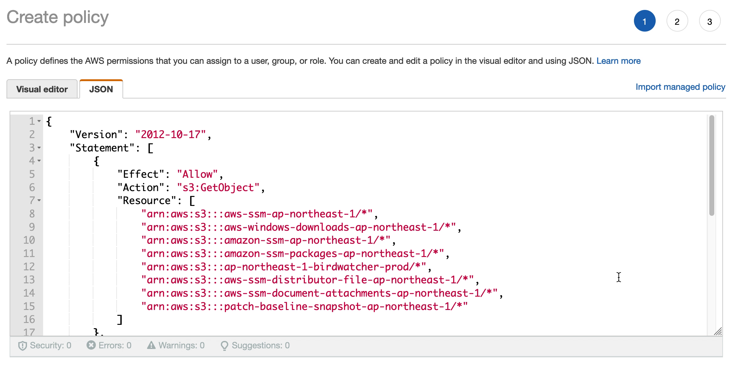
3. Creating the S3 bucket policy in IAM
The S3 bucket created in step 2 need a policy to allow SSM to access it. This policy will be created in IAM and then attached to the IAM roles used in both cloud native and VMware Cloud on AWS environments. Note that while this is a policy for S3 access, it is created in IAM and not in the S3 console.
The policy is created based on the JSON document below. Please update “YOUR-REGION” and “YOUR-BUCKET-NAME” with the relevant values for your environment.
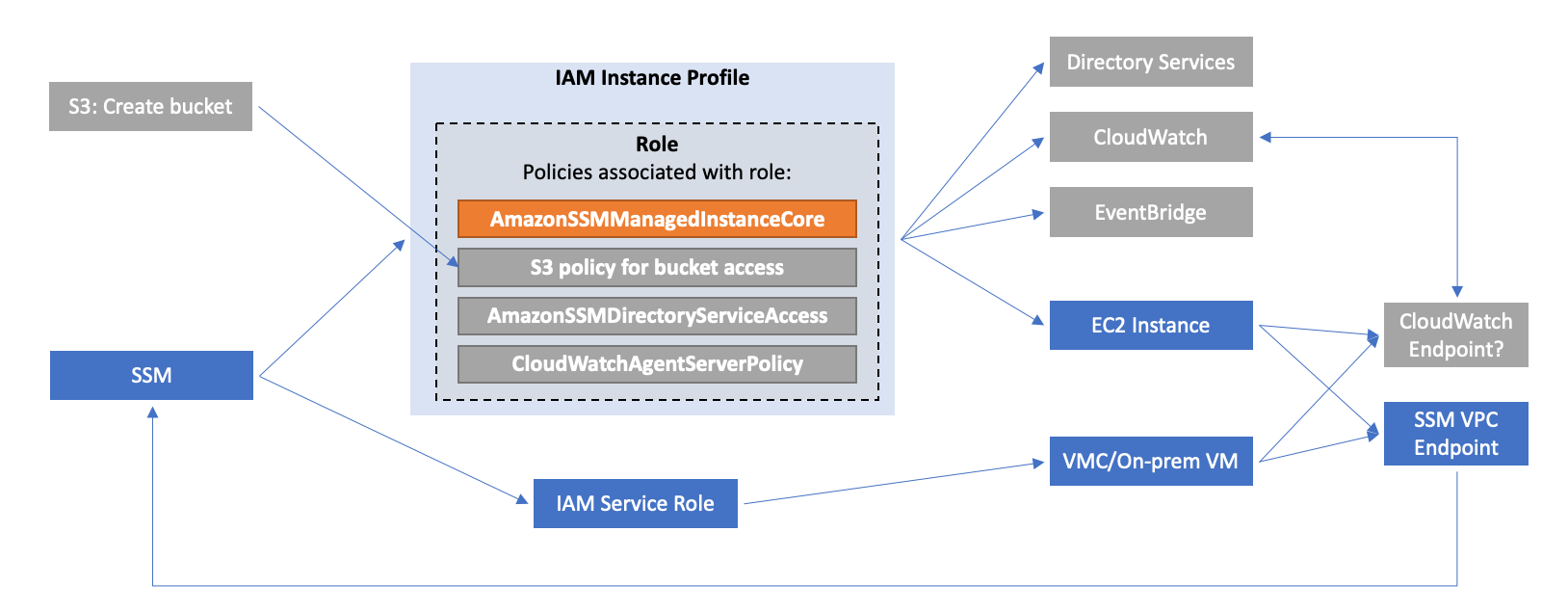
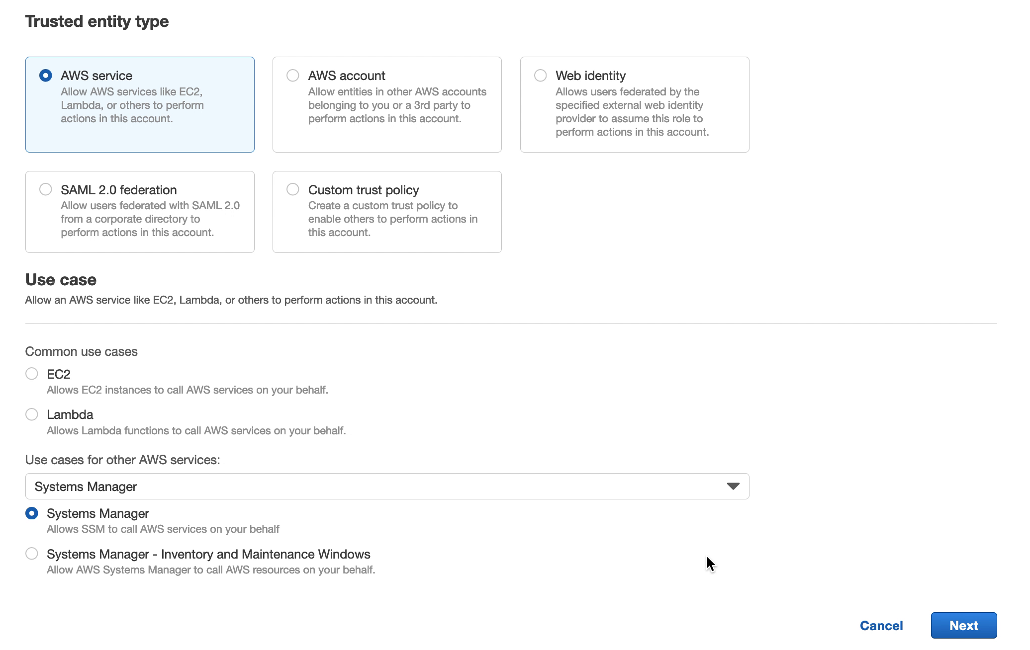
AWS Systems Manager can cover the management of both EC2 instances as well as VMware Cloud on AWS VMs. Each of these instance / VM types require a role created for them in IAM. This is to give the instance / VM the ability to interact with SSM and vice-versa. Detailed steps for this is covered in the AWS SSM user guide. In this section we will cover how to quickly get the VMware Cloud on AWS VM role created for use with hybrid activations in SSM.
Navigate to IAM in the AWS Console and create a new role. Select “Trusted entity type” to be “AWS Service” and the “Use Case” to be “Systems Manager”.
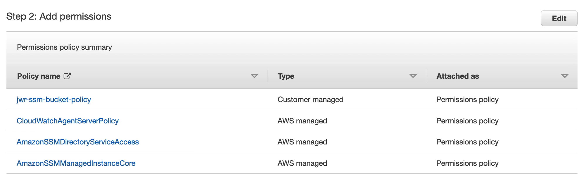
Under Permissions, search for and select the following:
CloudWatchAgentServerPolicy
AmazonSSMDirectoryServiceAccess
AmazonSSMManagedInstanceCore
The policy previously created for the SSM S3 bucket
5. Creating the systems manager VPC endpoints
Endpoints for AWS SSM can be created in the VMware Cloud on AWS Connected VPC. This is to provide the VMs in VMware Cloud on AWS a path to communicate with AWS SSM via the connected VPC ENI rather than accessing AWS SSM over the internet. This is both secure and as long as the SSM endpoint in the connected VPC is in the same availability zone as the VMware Cloud on AWS SDDC, communication is free of charge.
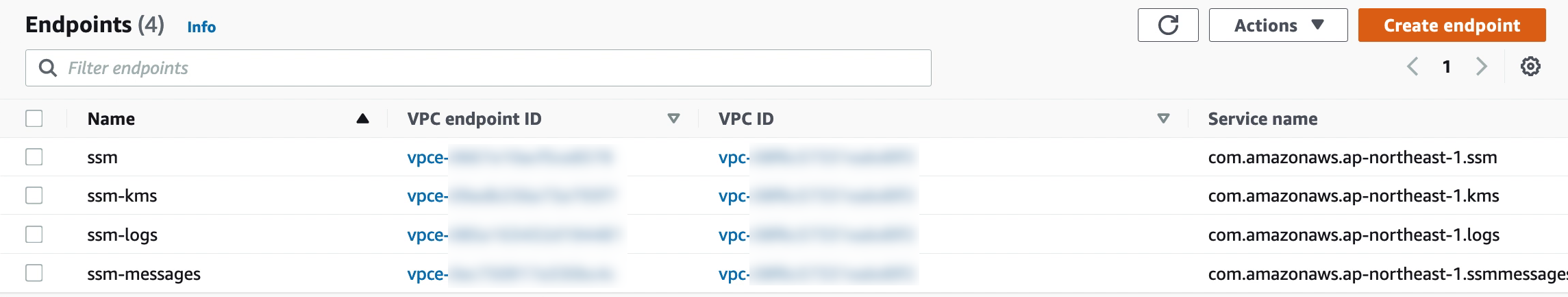
Create endpoints for the SSM service and, optionally, also KMS, Logs and SSM messages services as per the below:
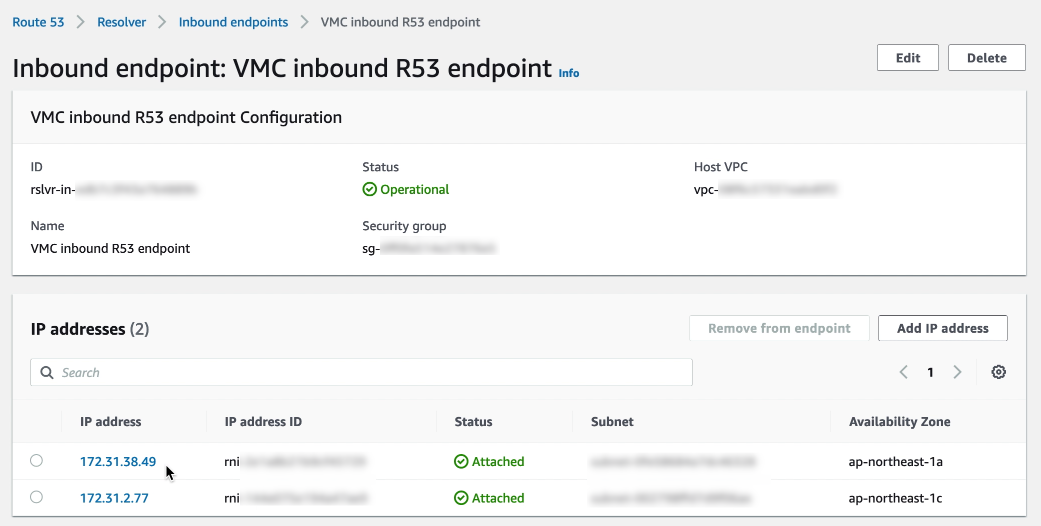
6. Creating the R53 DNS inbound endpoint
Creating the SSM endpoint is the first step but the VMs in VMware Cloud on AWS must also be directed to that endpoint rather than the public SSM IP addresses. Rather than modifying each VM, a more efficient way is to add a Route 53 inbound endpoint to the Connected VPC. If the CGW DHCP server for the VMware Cloud on AWS VM segments is then updated to point DNS to that Route 53 endpoint, the VMs will automatically resolve the SSM FQDN to the endpoint private IP address.
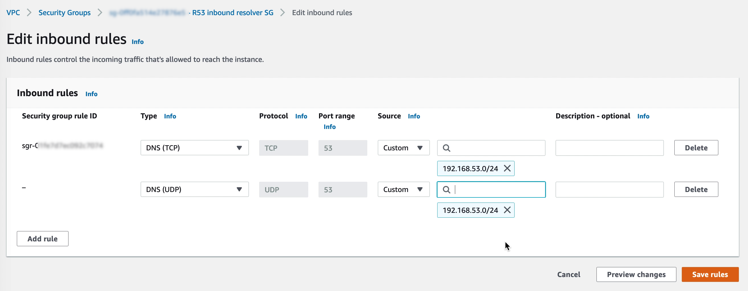
Make sure that the security group for the inbound R53 endpoints allow DNS on both TCP and UDP from the VMware Cloud on AWS CGW network segments.
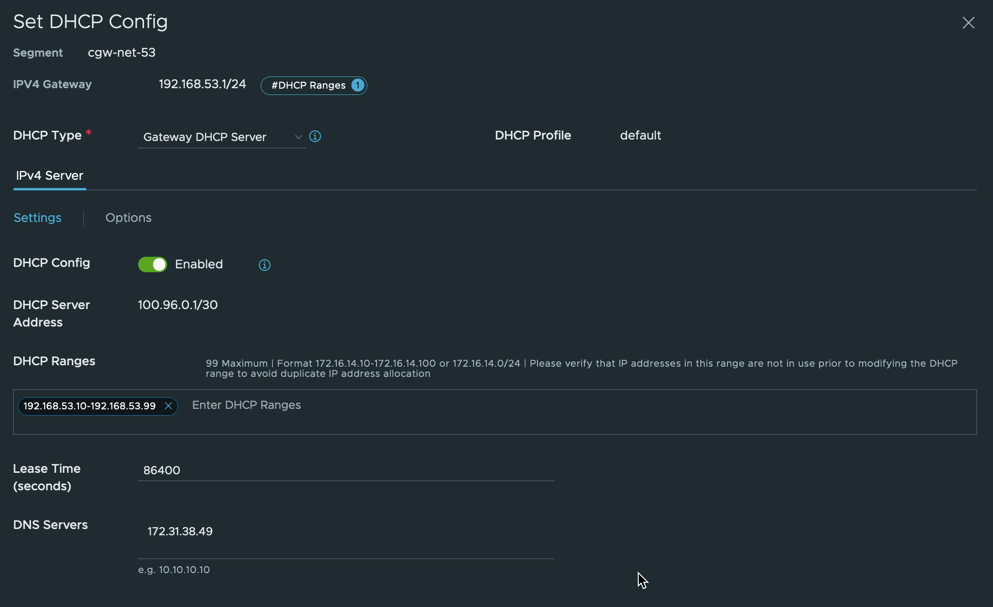
7. Pointing CGW DNS to R53
In the VMware Cloud on AWS console, navigate to “Networking & Security” and select “Segments” under Network. Update the network segments for the VMs to use the R53 inbound endpoint IP addresses.
The VMs connected to the CGW network segment may need to be disconnected and then re-connected to the network in vCenter or restart the networking from the OS side for the changes to take effect.
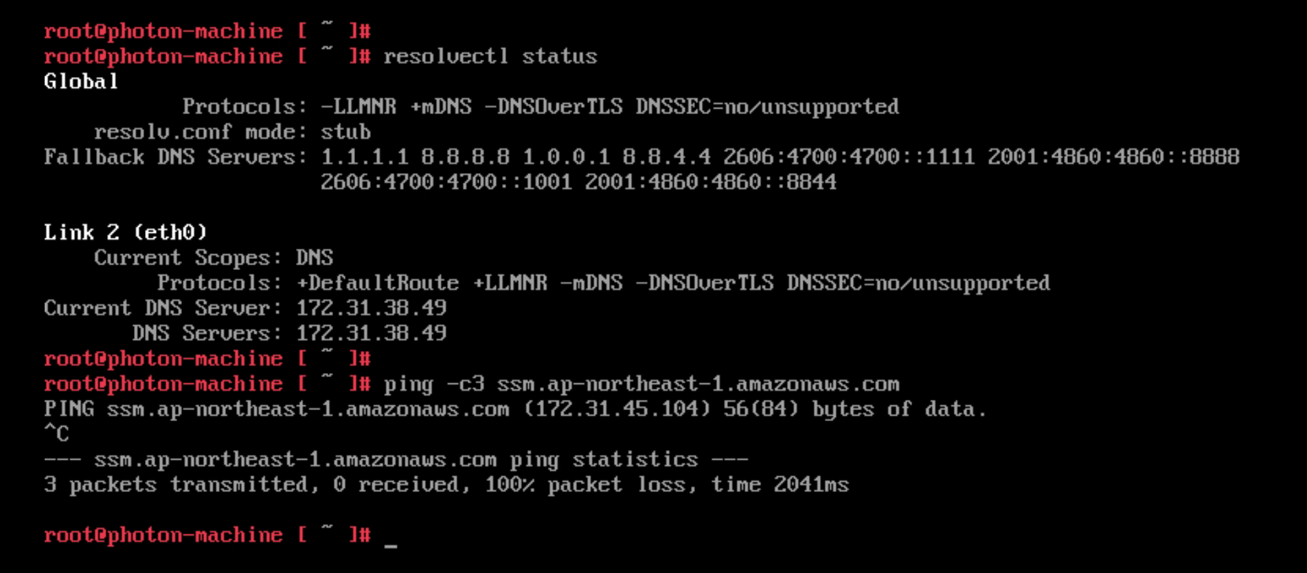
Before changing the DNS to point to the R53 inbound endpoint the VM in VMware Cloud on AWS resolves the regional SSM endpoint to the public IP address. Communication is done via the IGW in the VMware Cloud on AWS environment.
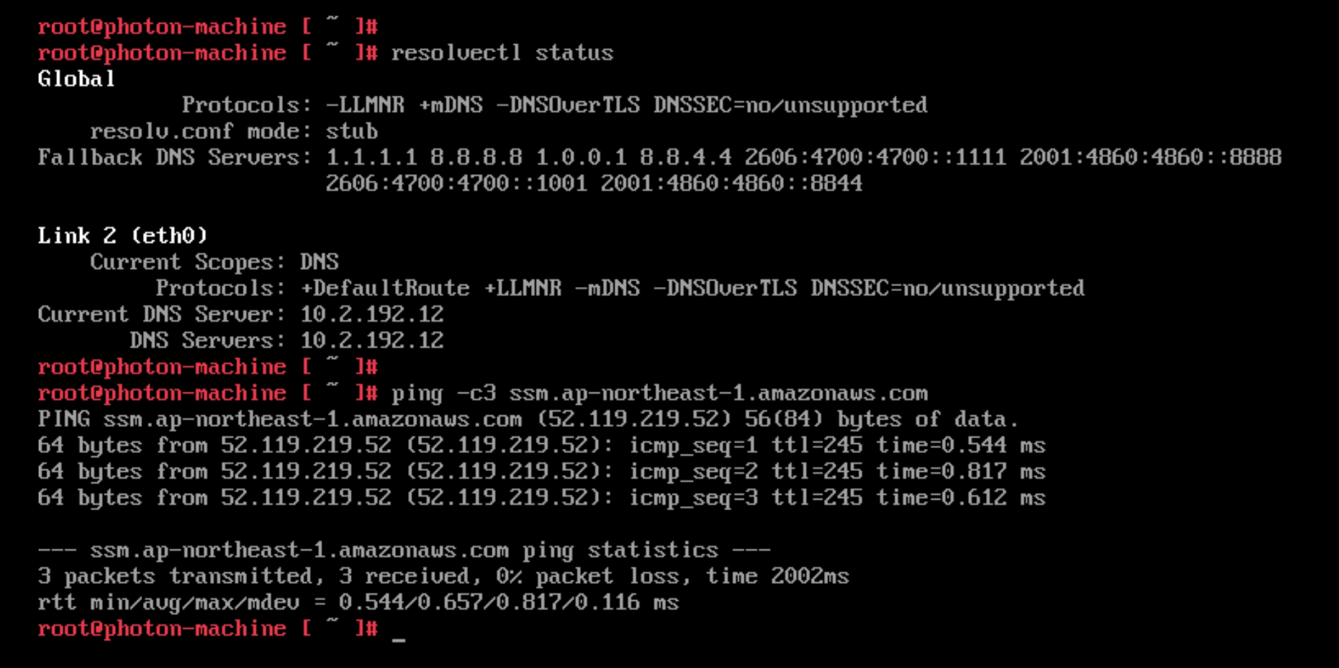
After updating the DNS the VM resolves the SSM endpoint to the private endpoint created earlier. Communication is over the Connected VPC ENI. Note: The ping doesn’t succeed since the security group for SSM blocks ICMP. However, the command shows that the VM correctly resolves the regional SSM endpoint to the private IP address in the Connected VPC.
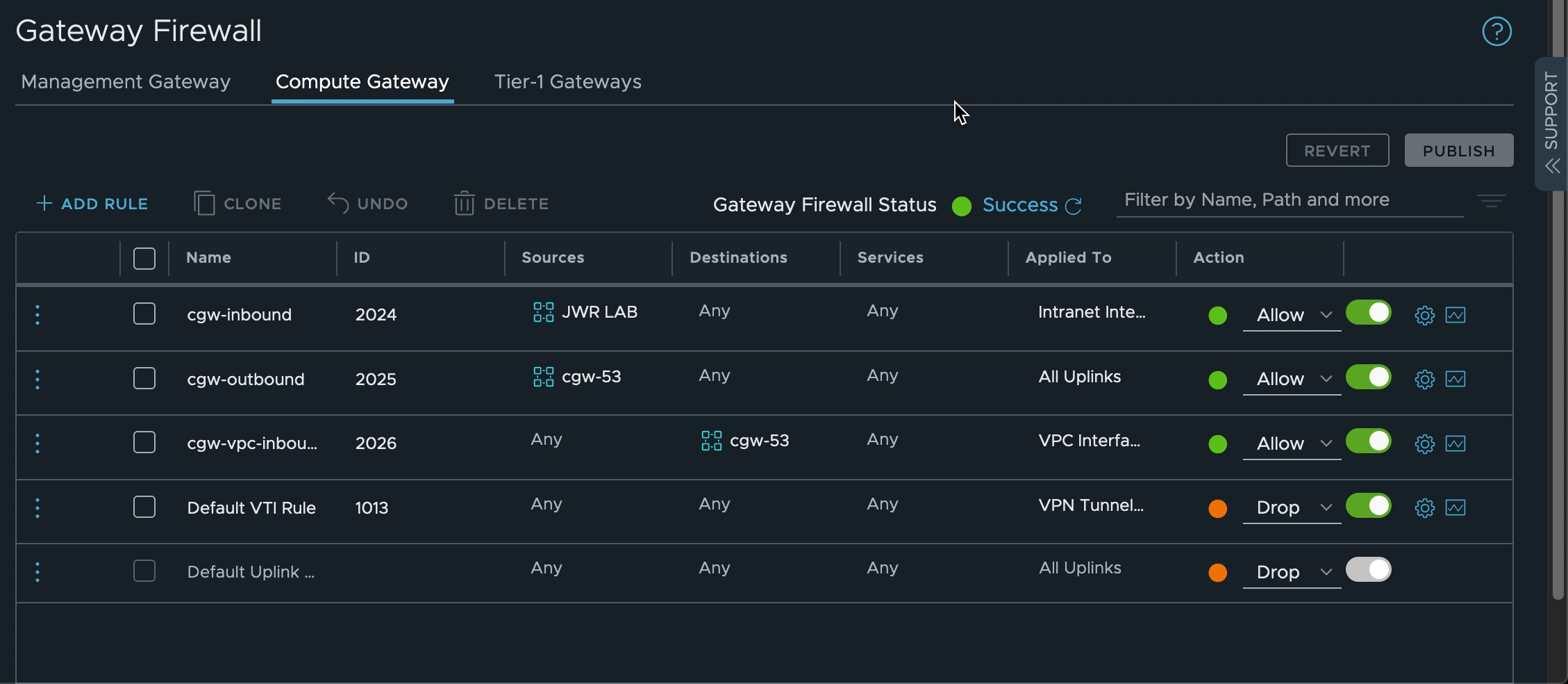
8. Creating the SDDC firewall rules
The network segments connected to the VMware Cloud on AWS CGW router need access to both SSM and R53 services in the Connected VPC. AWS SSM also need to be able to access the VMware Cloud on AWS VMs over the Connected VPC ENI. Create firewall rules on the CGW to allow this traffic. In the screenshot below the VMware Cloud on AWS VM network “cgw-53” is allowed to communicate anywhere over any uplink while inbound traffic to the same network is allowed over the VPC interface only.
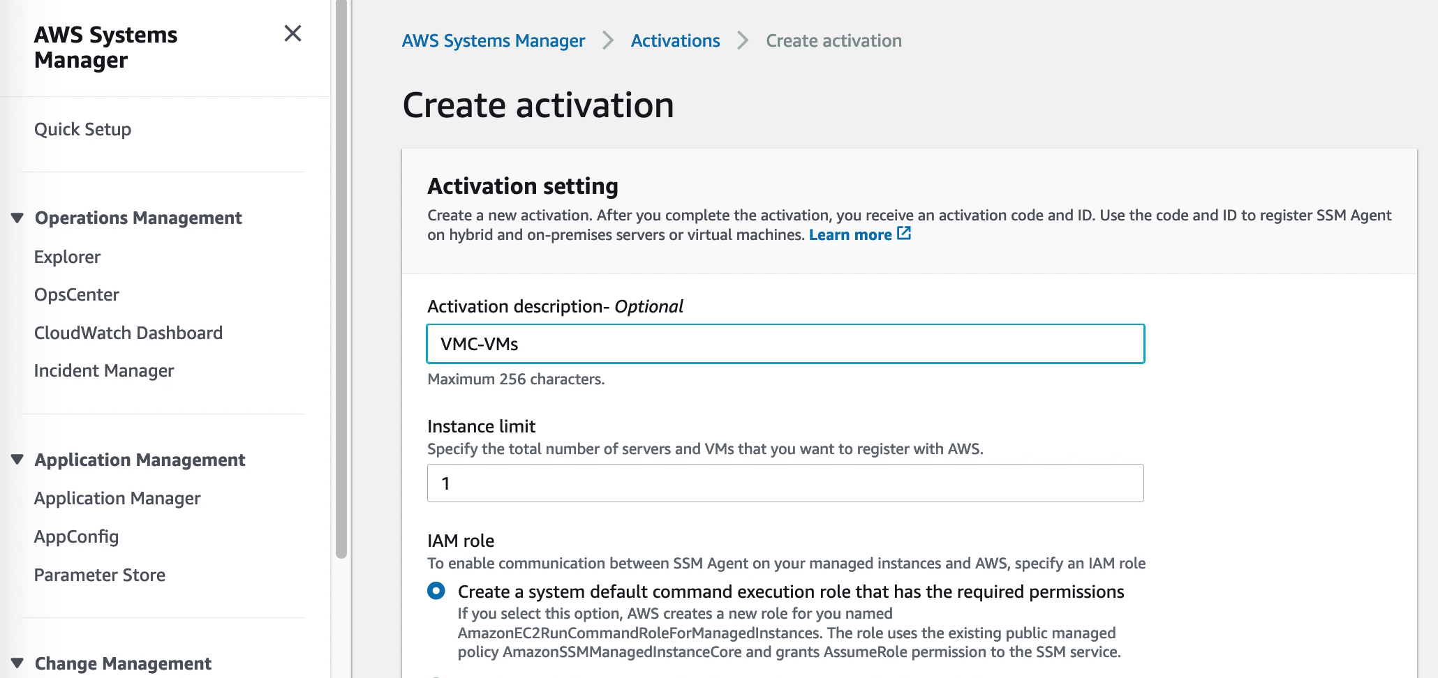
9. Creating a hybrid activation
Virtual machines external to EC2 are added to AWS SSM through a “Hybrid activation”. This is created via the SSM section of the AWS Console and generates an ID and a code for a preset number of VMs. These can be used as credentials in the next step where the SSM agent is installed and the VMs are registered with SSM
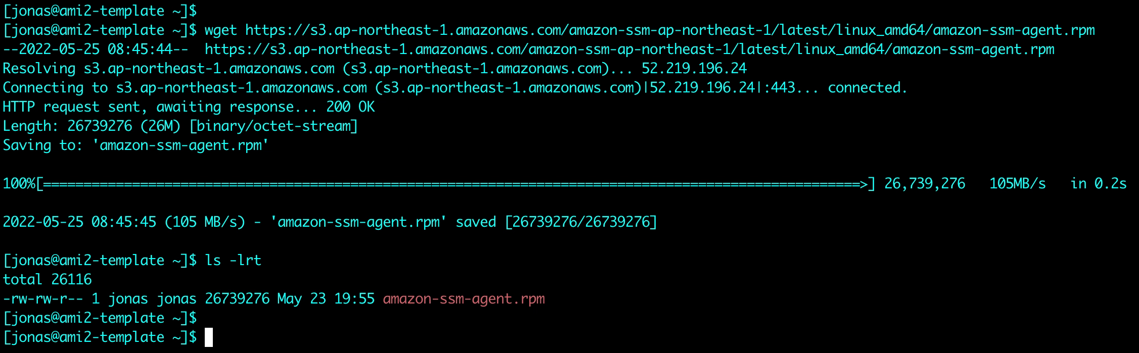
10. VM configuration: Installing the SSM agent and registering with SSM
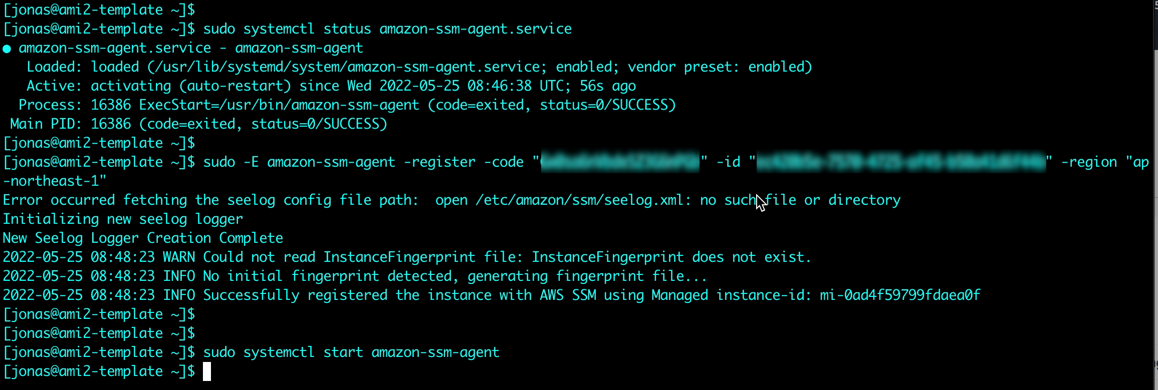
Instances on EC2 normally come with the SSM agent pre-installed. For VMs in VMware Cloud on AWS or on-premises VMware environments the agent needs to be installed. This is both quick and easy to do. The details for agent installation for a multitude of OS types are described in the SSM user guide. In this example the agent will be installed on a Linux VM. Instructions for Windows VMs can be found here.
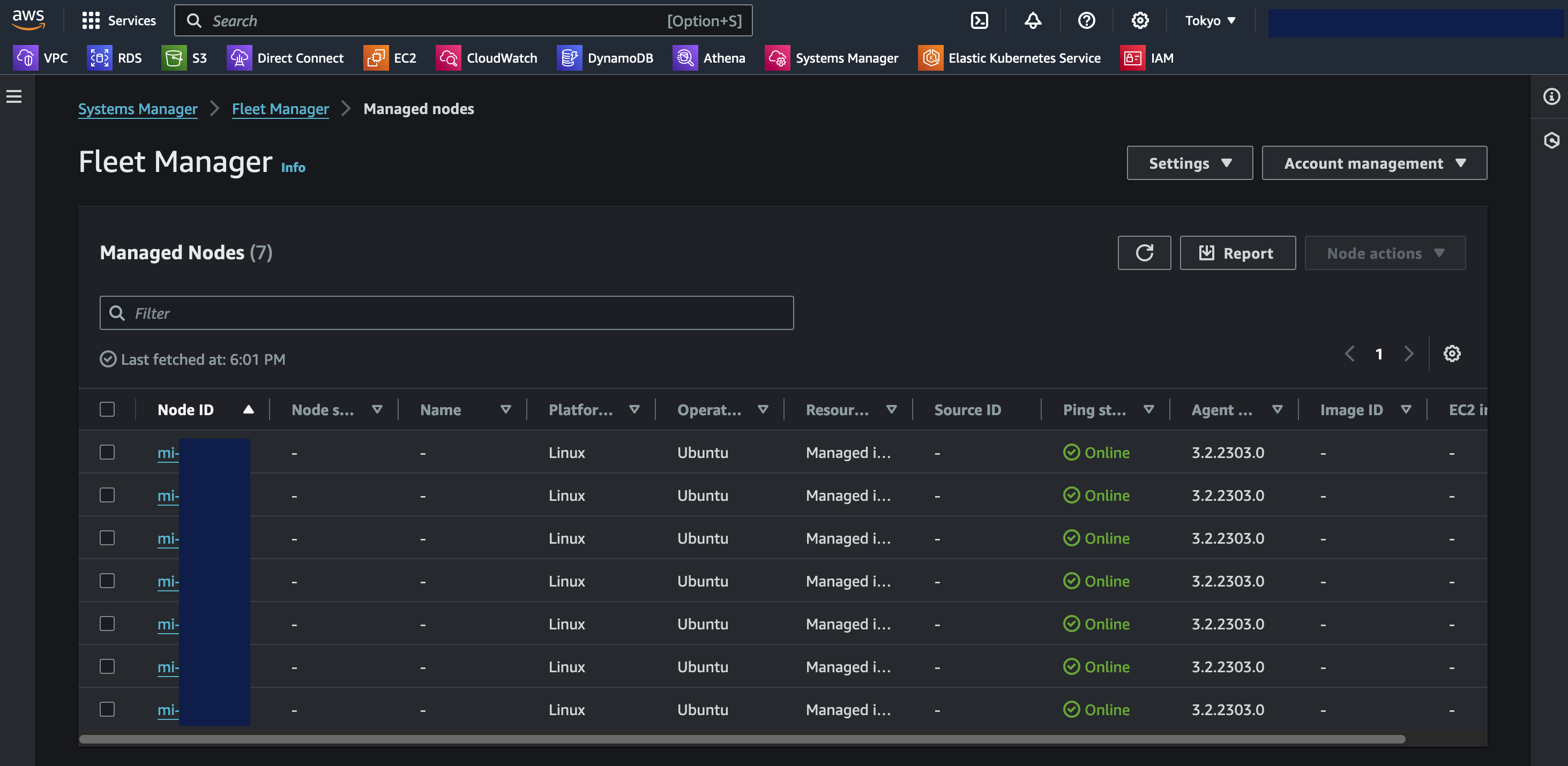
After downloading and installing the agent, the Hybrid Activation code and ID from step 9 above are used to register the VM with AWS SSM
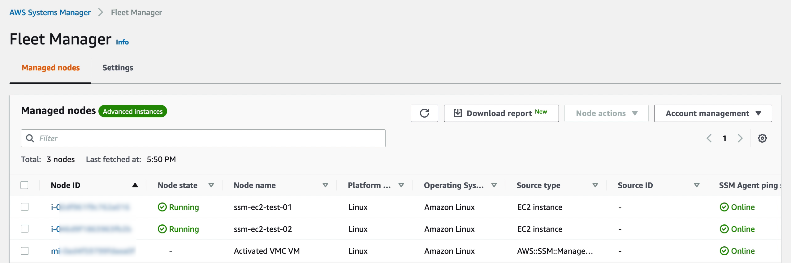
Verifying that the VM is available in Systems Manager. Note that in contrast from EC2 instances, the VMware Cloud on AWS VM is prefixed with an “mi-” rather than just an “i-”. This is an indication it is a Managed Instance external to EC2. Of course labels and groups can also be used to keep the managed nodes apart, but the Node ID is a quick indicator of where it comes from.
Managing the VMs in Systems Manager
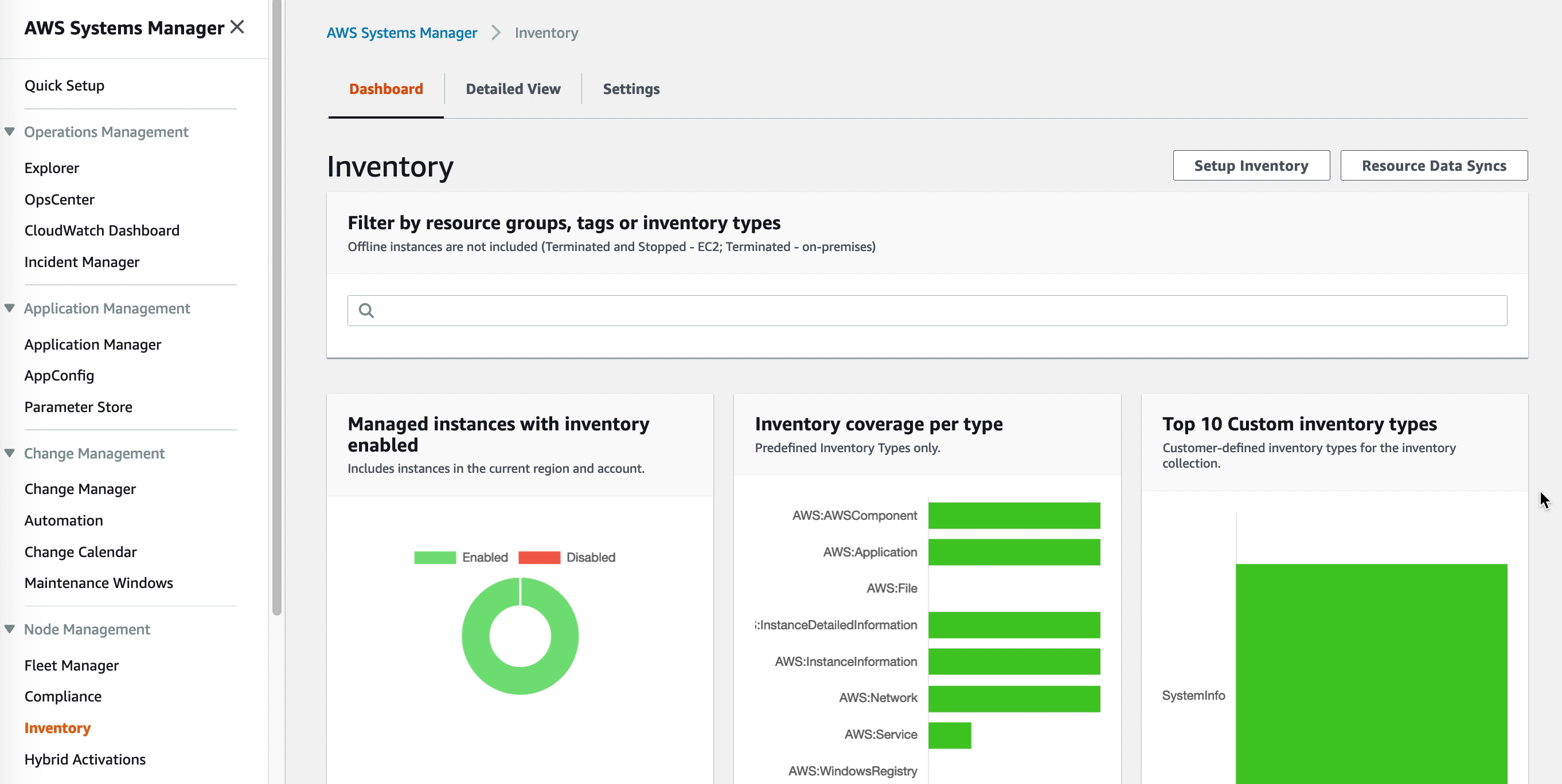
Viewing the VM inventory
Once the AWS SSM agent is installed it will start collecting the software inventory of the VM. This data is available through the SSM Inventory console but can also be exported to S3 for further processing by Athena. Detailed reports can be created by pointing QuickSight to the Athena data.
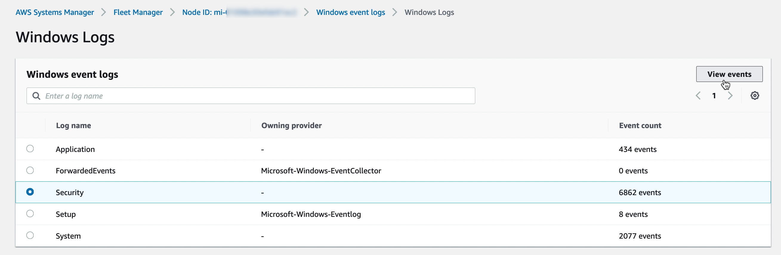
Accessing VM registry, logs and filesystem
The VM filesystem, performance metrics, system logs and even registry for Windows VMs is accessible directly through the AWS Console for each VM registered with SSM. Administering the VMs though the AWS Console reduces the need for direct desktop or shell access. For some features, like performance metrics, please be sure to enable KMS encryption in the SSM general settings.
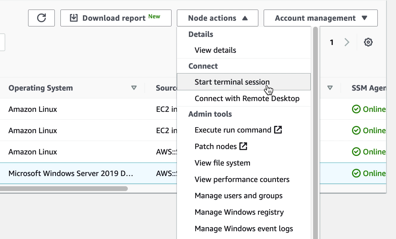
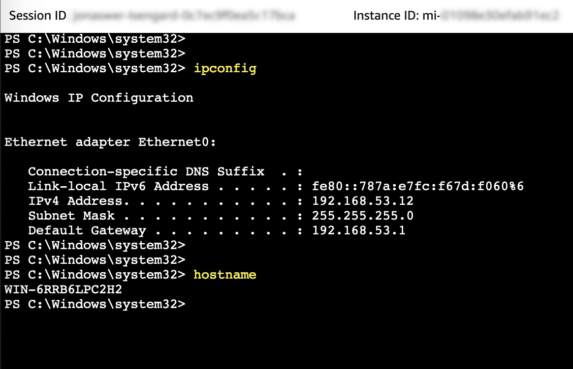
Accessing the VM PowerShell console
While PowerShell or a shell prompt on a VM can be accessed over RDP or SSH, having the ability to quickly connect to a VM console through SSM helps streamline system administration.
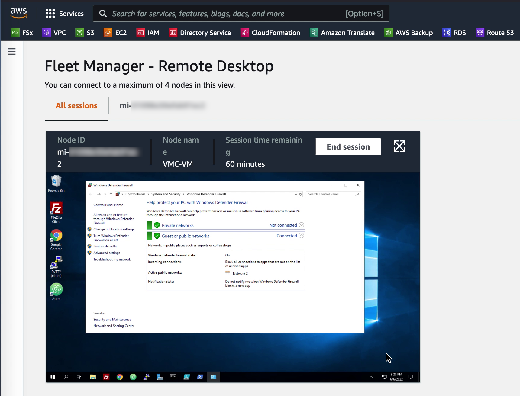
Accessing the VM desktop
For Windows VMs it is possible to quickly open an RDP session even though the firewall on the VM is enabled and blocking RDP. The SSM agent creates a loopback connection which enables access from the AWS console. Up to four sessions can be opened in a single SSM Session Manager window. The session window can be maximized to view the VM in full screen
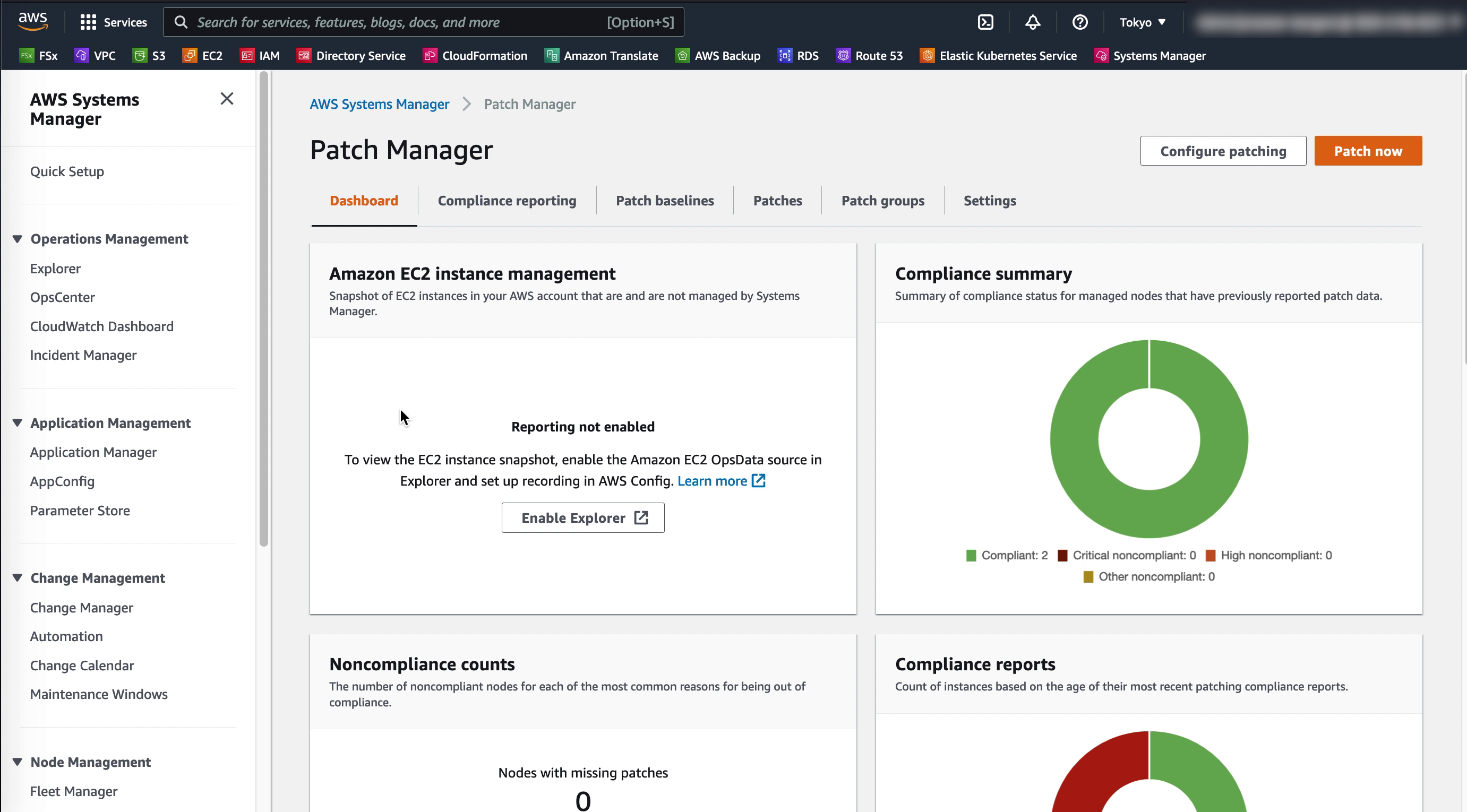
Patching VMs
Through SSM Patch manager, patch baselines and maintenance windows can easily be created and applied to the managed VMware VMs as well as EC2 instances to ensure they are up to date and have the highest level of protection possible
Conclusion
VMware Cloud on AWS is not a standalone solution but integrates well with a variety of AWS native services. In this blog post AWS Systems Manager and related services were leveraged to enhance security of VMs running on VMware Cloud on AWS by centralizing access controls and automating OS patch management.