Migrate from EC2 to NC2 and perform DR failover between two AWS regions without changing IP addresses

Some customers require cross-region disaster recovery (DR) in AWS but often face the challenge of changing IP addresses during a failover to another region. This change can disrupt external access to services running on instances covered by the DR policy.

Nutanix Cloud Clusters (NC2) address this challenge with built-in DR functionality that ensures IP addresses remain consistent during failovers between regions. Bonus: It is possible to over-provision CPU on NC2, so it may actually be possible to save on compute costs after the migration to NC2. However it can only retain IP addresses during DR for workloads which are already residing on a Nutanix cluster, so we have to migrate the EC2 instances first.

The free Nutanix Move migration tool can migrate workloads from Amazon EC2 to Nutanix Cloud Clusters, though it currently lacks support for IP retention. In this blog we use some creative workarounds to maintain consistent IPs throughout the migration, although note that MAC addresses will change. NC2 then retains the IPs during regional failovers as part of the Nutanix DR solution. Let’s dive in!

Software versions used during testing

AOS6.10
Prism Centralpc.2024.2

Solution architecture

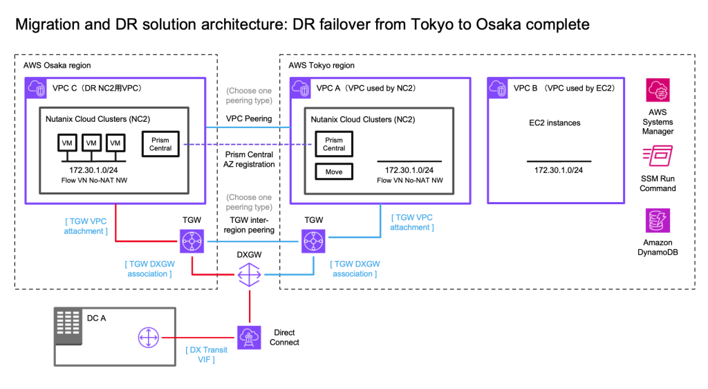
In this case we have an on-premises datacenter (DC), an AWS VPC with EC2 instances which we want to have covered by a DR policy (so they can fail over to another region without changing IP addresses) and finally two NC2 clusters – one in the primary region and one in a separate region for DR purposes. We use Tokyo (ap-northeast-1) as the primary AWS region and Osaka (ap-northeast-3) as the disaster recovery location in this example.
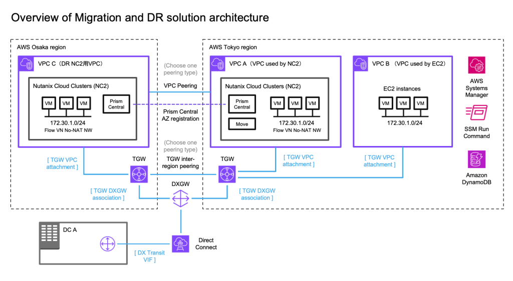
Overview of solution architecture. Click to embiggen.

We illustrate connectivity to the on-premises environment by using Direct Connect. Note that all the testing of this solution has been done with S2S VPN attached to the TGW’s in each region. Peering between the two DR locations can be done by using cross-region VPC peering or peering of two Transit Gateways (TGW).

Networking

To retain the IP addresses of the migrated EC2 instances we use Flow Virtual Networking (FVN) to create overlay no-NAT overlay networks on NC2 with a CIDR range which matches that of the original subnet the EC2 instances are connected to. We create this overlay network in both Tokyo and Osaka NC2 clusters so that we can later fail over the VMs and have them attach to a network with the same CIDR range.

To ensure the on-premises DC is able to access the VMs we modify the route tables throughout the process. That way we maintain routes which point to the migrated EC2 instances, regardless of where they are located.

Automating the VPC and TGW creation with Terraform / Open Tofu

In the case you’d like to try this out yourself, the Terraform / Open Tofu templates for deploying the VPC’s, TGW’s and the routing for these can be found on GitHub here:

https://github.com/jonas-werner/aws-dual-region-peered-tgw-with-vpcs-for-nc2-dr

When to use which peering type for inter-region connectivity

Generally it can be said that VPC Peering is better for lower traffic scenarios or when the simplicity of direct peering is desirable, despite slightly higher data transfer costs incurred for VPC peering.

TGW Peering is more cost-efficient for high-traffic environments or complex architectures, where the centralized management and lower data transfer rates outweigh the additional costs per TGW attachment. Note that although traffic passes through two TGW’s, the peering interface doesn’t incur data transfer charges so the data is only charged once (roughly 0.02 cents / GiB in the Tokyo region).

The workaround for IP retention

As mentioned in the introduction, while the Nutanix Move virtual appliance is very capable at migrating from EC2 to NC2, it is at time of writing unable to retain the IP addresses of the workloads it migrates. To work around this we do the following:

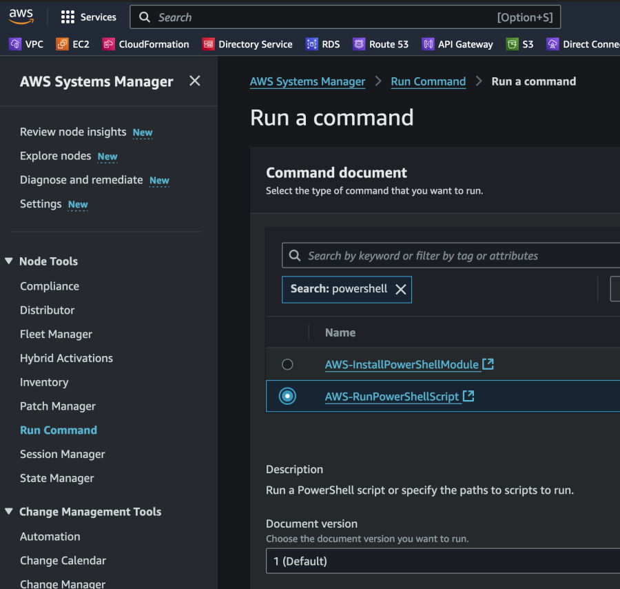
  1. Prior to the migration we use AWS Systems Manager (SSM) to run a PowerShell or Bash script on the instances to be migrated. The script captures the EC2 instances ID, hostname and local IP address and stores that information into a DynamoDB table for use later
  2. We perform the migration from EC2 to NC2 using Nutanix Move. The IP address will change although we migrate the instance to a Flow Virtual Networking (FVN) overlay network with the same CIDR range as the original network the EC2 instances are connected to.
  3. We run a Python script which uses the DymamoDB information as a template and then connects to the Nutanix Prism Central API. It then removes the existing network interface and adds a new one with the correct (original) IP address to each of the migrated instances.

Once the instances are migrated to NC2 the process of configuring DR between Tokyo and Osaka regions is trivial.

You can download the PowerShell and Python scripts used in this blog on GitHub:

https://github.com/jonas-werner/EC2-to-NC2-with-IP-preservation/tree/main

Step 1: Capture IP addresses of the EC2 instances

In this step we prepare for the migration from EC2 to NC2. The initial state of the network, the workloads and the route to the 172.30.1.0/24 network is as illustrated by the red line in the below diagram.
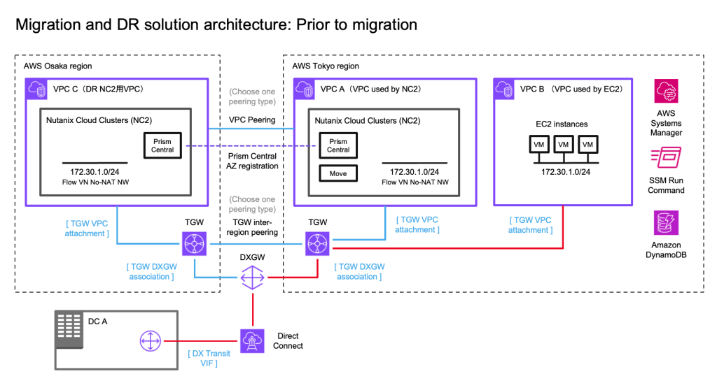
To start with we gather information about the EC2 instances and store that info in DynamoDB. In the name of efficiency we use the SSM Run command to execute the PowerShell script. This makes it easy to get this done in a single go (or two “goes” if we do both Windows and Linux workloads). We test with a single Windows 2019 Server EC2 instance in this example.

First create a DynamoDB table to hold this information. Nothing special is required for this table as long as it is accessible to SSM as it runs the script. We need to give the IAM role used when running SSM commands access to DynamoDB of course, so we add the following permissions to the standard SSM role:

        {
            "Sid": "AllowDynamoDBAccess",
            "Effect": "Allow",
            "Action": [
                "dynamodb:PutItem"
            ],
            "Resource": "arn:aws:dynamodb:<your-aws-region>:<your-aws-account>:table/<dynamodb-table-name>"
        },

In order to collect the instance name from meta data we enable the “Allow tags in instance metadata” setting in the EC2 console. This is important as we will use the “Name” tag in EC2 as the Key to look up the instance in NC2 post-migration. Of course other methods could be used – most obviously the name of the instance itself. However in this case we use the EC2 name tag, as this is also how the VM will show up in NC2 post migration.
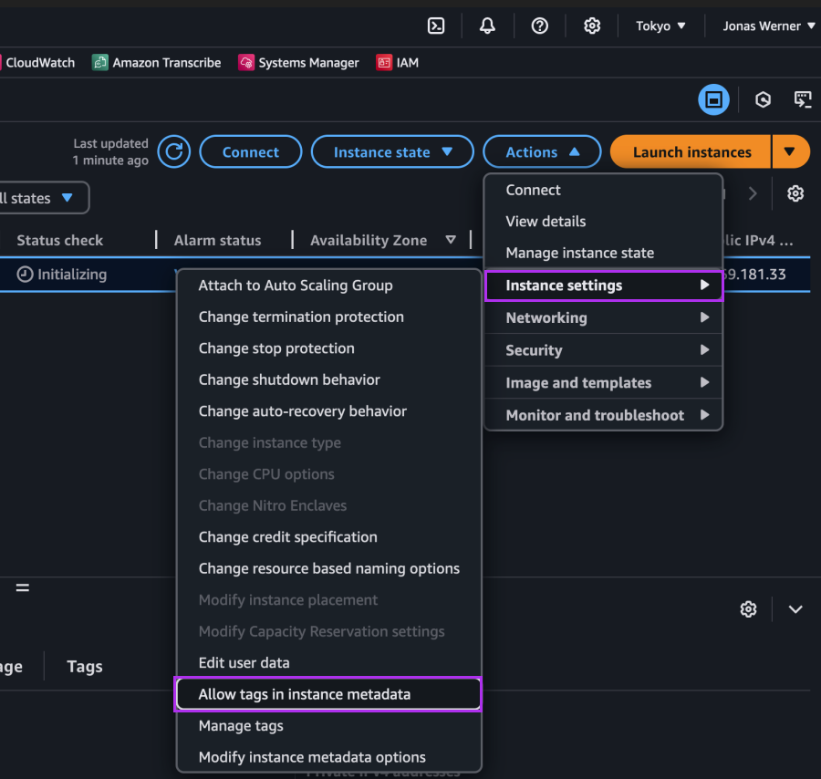
The we execute the script on our instances through the SSM Run command as follows
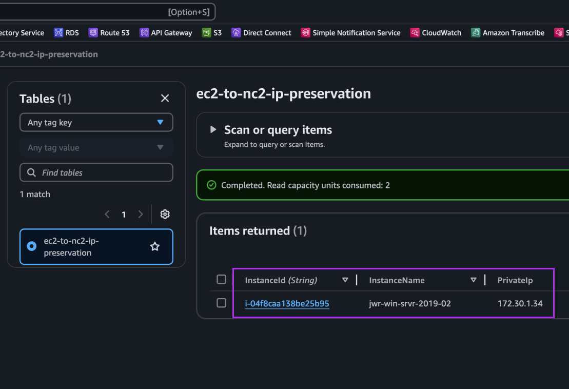
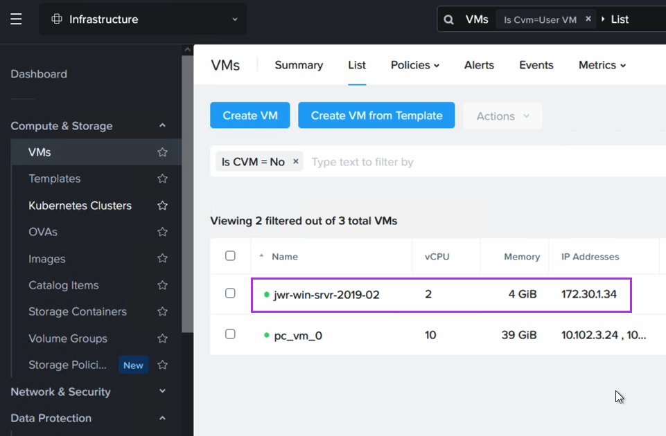
After execution we can see an entry for our Windows EC2 instance showing its instance ID, hostname and IP address: 172.30.1.34. This is the IP we want to retain.
That’s all for this section. Next we perform the migration from EC2 to NC2.

Step 2: Migrating from EC2 to NC2

For the migration we have deployed Nutanix Move on the NC2 cluster. We have also created an FVN overlay no-NAT network with the same CIDR as the subnet the EC2 instance is connected to, although the DHCP range is set to avoid any of the IPs currently used by instances on that subnet.

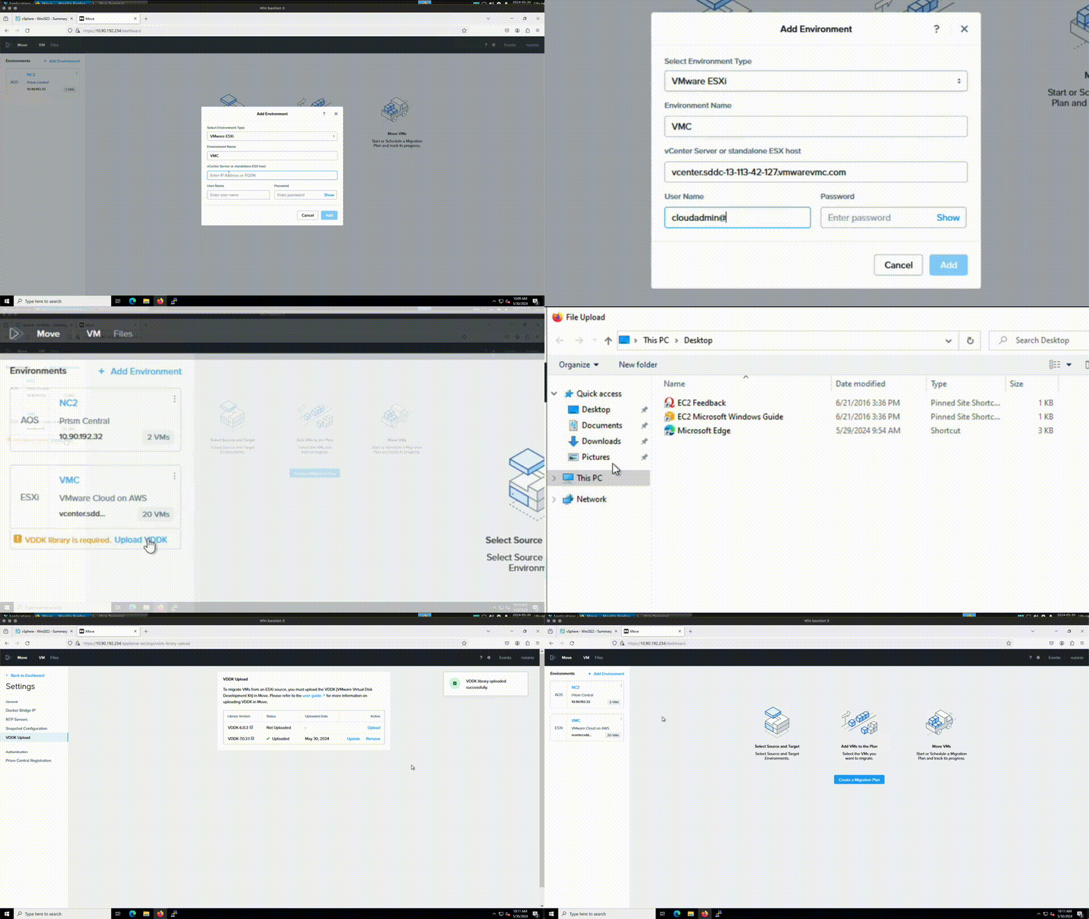
Move has the NC2 cluster and the AWS environment added in as migration sources / targets.
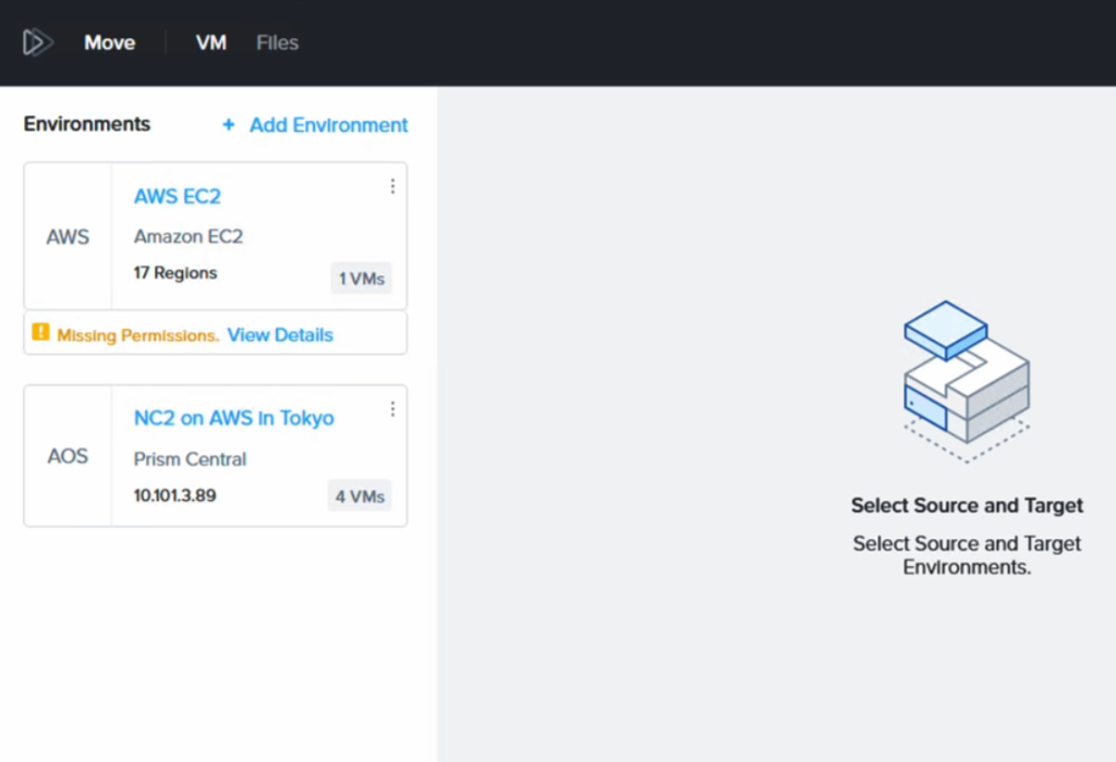
It complains about “missing permissions” but this is because we have only given it permission to migrate FROM EC2, not TO EC2. Since that is all we want to do, this is fine. Please refer to the Move manual for details on the AWS IAM policy required depending on your use case.

Post migration the VM will have a different IP address (taken from the DHCP range on the FVN subnet it is connected to).
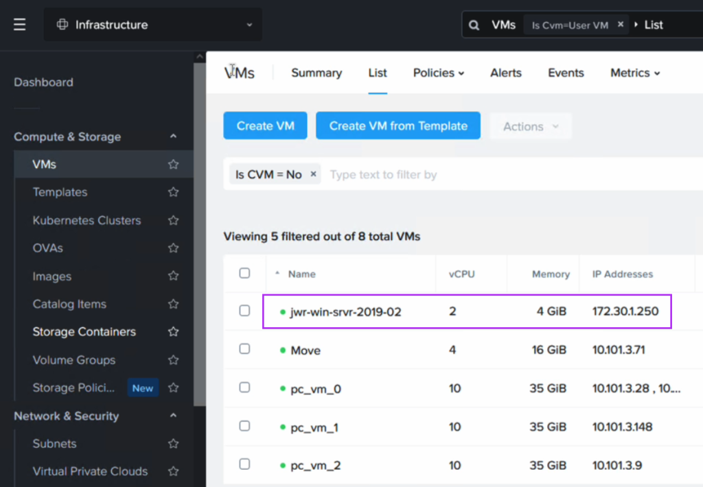
We use a Python script in the next section to revert the IP address to what it was while running as an EC2 instance.

Step 3: Revert the IP address to match what the EC2 instance had originally

Now we execute a Python script which will look up the instance name in DynamoDB, match it with the VM name in NC2 and then remove and re-create the network interface using the Prism Central API. The new interface will have the original IP configured as a static address.

The script can be downloaded from GitHub here. Please export the Prism Central username and password as environment variables to run the script. Also update the Prism Central IP and the subnet name to match the one used in your environment as well as the AWS region and the DynamoDB table name.
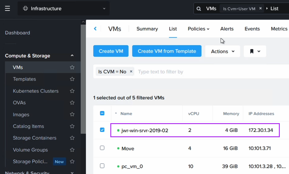
After running the script we can now verify that the VM has received its original IP address. Note that since we have replaced the NIC in this process, the IP is the same as before, but the MAC address will have changed.

Routing after migration from EC2 to NC2 in Tokyo

Now that the VM exists on NC2 we need to update our routing to ensure that traffic is directed to this VM and not the original EC2 instance (which has now been shut down by Move after the migration).

To do this we disconnect the EC2 VPC from the TGW and add the subnet as a static route in the TGW, this time pointing to the NC2 VPC rather than the EC2 VPC. The subnet should already exist as an “Allowed prefix” on the DXGW, so that part can be left as-is.
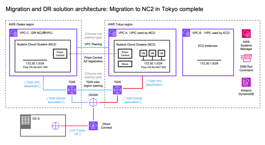
The attachments highlighted in red shows the active route to the 172.30.1.0/24 subnet, which has now been changed to point to the NC2 VPC. Since the subnet is a FVN no-NAT subnet it will show up in the NC2 VPC route table.

Wrapping up the migration part

Now our EC2 instance has been migrated to NC2. Its IP address is intact and since we have updated the routing between AWS and the on-premises DC, the on-prem users can access the migrated instances just like they normally would. In fact, apart from the maintenance window for the migration, VM power-up on NC2 and the routing switch, they are unlikely to notice that their former EC2 instance is now running on another platform.

Configuring DR between the Tokyo and Osaka NC2 clusters

At this point all we have left to do is set up the DR configuration between the two Nutanix clusters in Tokyo and Osaka. Since DR is a built-in component, this is very straight forward. We link the two Prism Central instances and of course create the FVN overlay network on the Osaka side as well to ensure we can keep the same CIDR range also after failover.
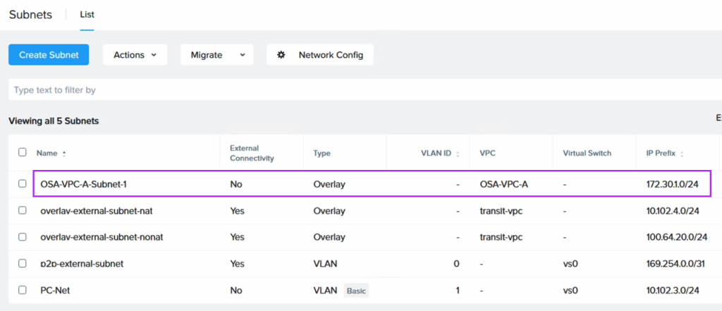
After enabling Disaster Recovery we can easily create the DR plan through Prism Central
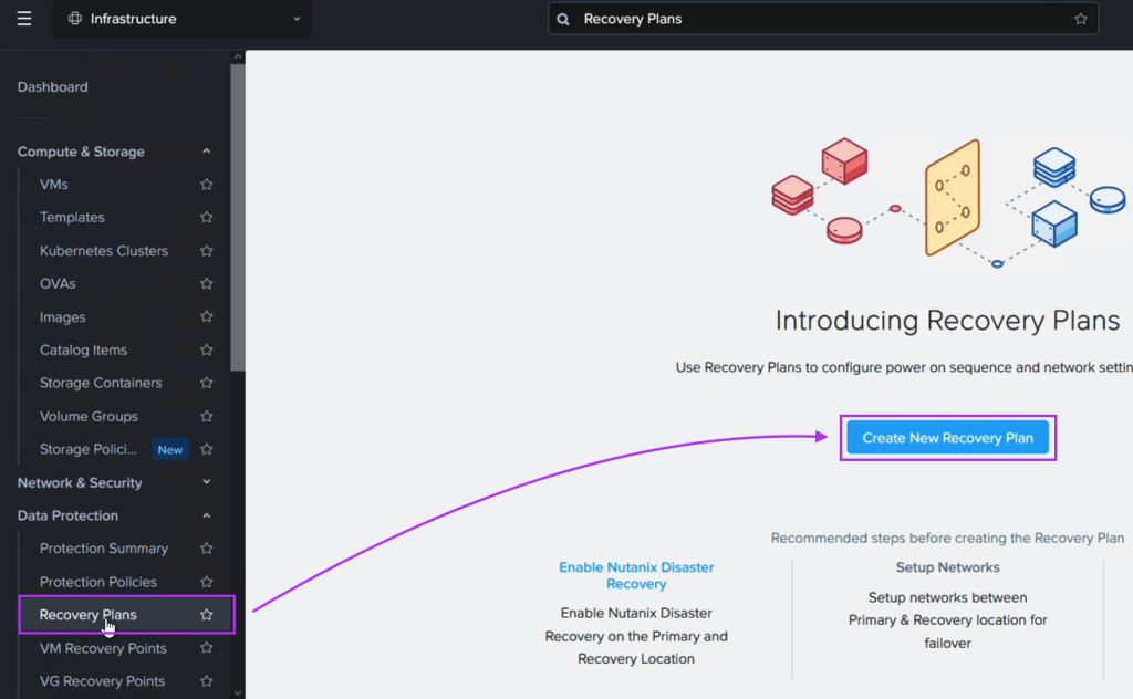
When we create the DR plan we set the VMs on the Tokyo network to fail over to its equivalent on the Osaka DR site
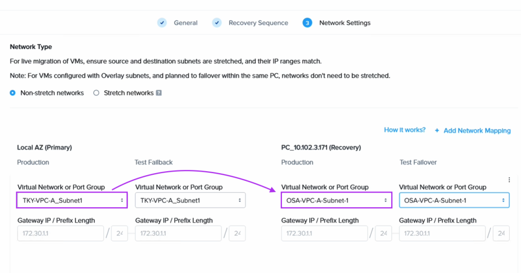
Finally we proceed to fail over our VM from NC2 in Tokyo to NC2 in Osaka
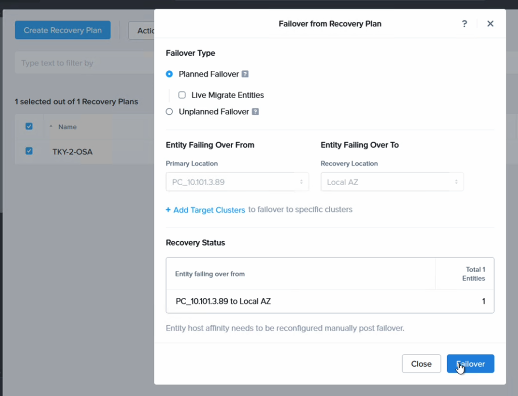
After failing over we can confirm that the VM is not only powered up in Osaka, but that it has also retained the IP address, as expected.
Updating the routing to point to Osaka rather than Tokyo

After failing over from Tokyo to Osaka we need to also update the routes pointing to the 172.30.1.0/24 network by modifying the TGW in Osaka. From a diagram perspective it will look like follows.
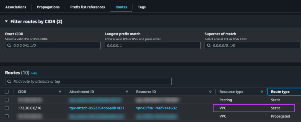
On the Osaka TGW we create a static route to the 172.30.0.0/16 network pointing to the Osaka NC2 VPC
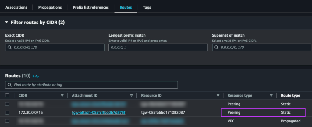
We also update the static route on the Tokyo TGW which points to the local NC2 VPC and instead set it to point to the peering connection to Osaka
Results and wrap-up

With these routing changes implemented it is now possible for users on the on-premises DC to continue to access the very same VMs with the very same IP addresses. This possible is even after those workloads have been migrated from EC2 to NC2 in Tokyo and then further having been failed over with a DR plan from Tokyo region to Osaka region.

Hope that was helpful! Please reach out to your local Nutanix representative for discussions if this type of solution is of interest. Thank you for reading!

Links

Migrating VMs from VMware Cloud on AWS (VMC) to Nutanix Cloud Clusters on AWS (NC2)

Summary

In this blog post we explore two ways to use Nutanix Move 5.3 to migrate Virtual Machines from an existing VMware Cloud on AWS (VMC) environment to Nutanix Cloud Clusters on AWS (NC2). This is done while preserving both IP and MAC addresses of the VMs being migrated.

The most straight forward method is to deploy NC2 into the Connected VPC. This is a VPC which is attached at time of deployment of the VMware Cloud on AWS environment and is owned by the customer. Alternatively, we can deploy NC2 into a completely separate VPC and connect to the VMware Cloud on AWS cluster through a VMware Transit Connect (VTGW).

Architecture overview

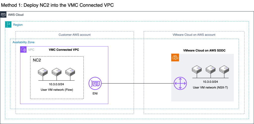
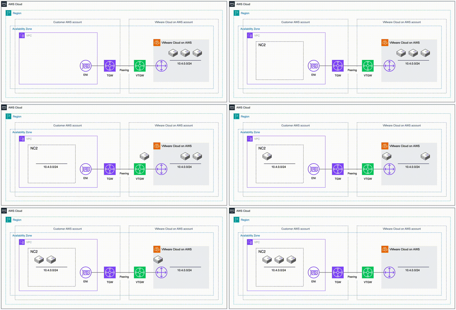
The two methods are illustrated below. Method 1 is recommended due to the ease of setup, simple networking and no data transfer charges. However, care need to be taken to ensure there is no overlap with any existing resources deployed into the Connected VPC. For example by creating new private subnets in the Connected VPC specifically for the NC2 deployment.

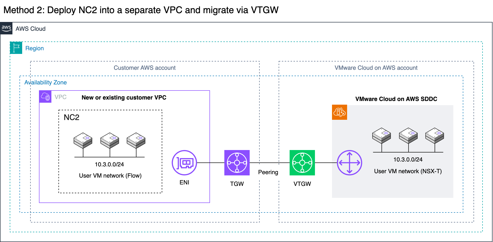
Method 2 covers migrating via a VMware Transit Connect (VTGW). Although it has additional routing considerations, this is also a fully viable option. In this example we peer the VTGW with a normal customer-controlled AWS Transit Gateway (TGW). Note that with Method 2 the VTGW can also connect directly to a VPC without the need for a TGW, but this will limit the routing options for the customer.

It’s important to keep in mind that both options can migrate VMs from VMC without changing IP or MAC addresses. Neither option require L2 Extension of user VM networks. This underlines the ease of which a migration like this can be done. There are of course some caveats. Refer to the VM networking section below for more detail.

Method 1: Migrate from VMC to NC2 deployed into the VMC Connected VPC
Method 2: Migrate VMs via VTGW into a separate or new VPC

VM networking

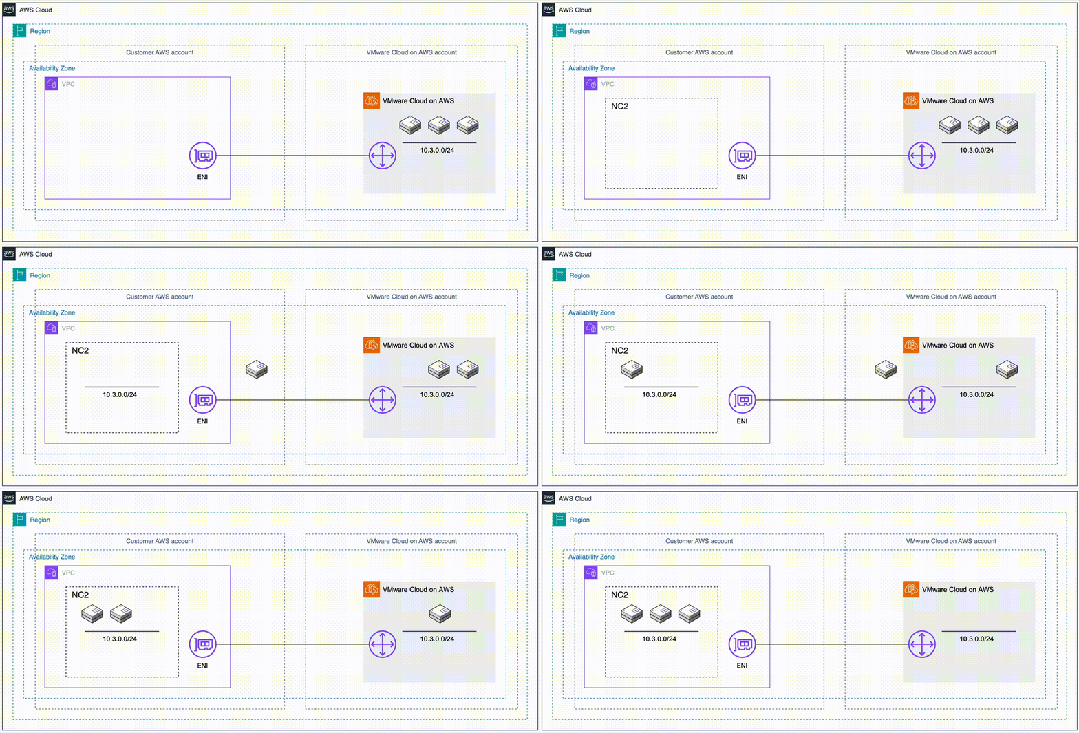
The whole migration can be done without L2 extension of VM networks. On the VMware Cloud on AWS side Virtual Machines in VMC are connected to overlay networks created with NSX-T using the VMC management console. These are represented by the “10.3.0.0/24” network in this example. The same CIDR ranges can be created as overlay networks by using Nutanix Flow on the NC2 cluster. Thereby, when VMs are migrated from VMC to NC2, they don’t need to change their IP or MAC addresses.

Note that if L2 Extension is not used, there is no communication between the overlay networks in NC2 and the overlay networks in VMC. Therefore, plan the migration so that VMs which need to communicate are moved together.

Also note that Flow does not advertise the overlay networks into the VPC route table. As long as VMware Cloud on AWS is attached to the connected VPC, the routes for the VMs will point to the active ENI created during the VMC cluster deployment. Destroying the VMC cluster will remove these ENIs and the corresponding routes from the Connected VPC route table.

Migration tool: Move

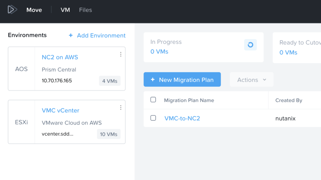
The Nutanix Move migration tool has with the recent 5.3 release added support for migrations from VMware Cloud on AWS. In this example, Move is deployed into the NC2 cluster. Both the VMC and the NC2 environments have been registered with Move and the inventories of both show up and are available for migration. More details in the Move deployment section below.

Method 1: Deploy NC2 into the Connected VPC

If there is enough space to deploy NC2 into the already existing Connected VPC in the customer account, this is the easiest and most straight-forward option. Connectivity and routing between the Connected VPC and the VMware Cloud on AWS environment is already configured as part of the VMC deployment. Do make sure that the CIDR ranges of any existing subnets are sufficient for deployment of NC2 and that there aren’t already resources deployed into those subnets which could interfere with the NC2 components. If the VPC CIDR range has space for new subnets, consider creating new private subnets to hold the NC2 deployment.

  • Benefits
    • No need to create new VPC and subnets
    • VPC is already connected to VMC and routing is configured
    • Data transfer is free of charge
    • High link / data transfer speed

  • Drawbacks
    • VPC may already be fully populated with resources
    • VPC may not have the correct CIDR ranges for NC2

Method 1: Steps to deploy

Simply sign up for NC2 or start a trial and deploy through the NC2 deployment wizard. Select the latest version – 6.8, to get Flow overlay networking and the centralized management through Prism Central included.

Note that NC2 can only be deployed into private AWS subnets and that internet connectivity need to be present. If no direct internet connectivity is available, proxy support is also available through the deployment wizard.

VMware Cloud on AWS automatically updates the default route table in the connected VPC with the routes to vCenter, ESXi and the user networks. However, if NC2 is deployed into a subnet which doesn’t use the default route table those routes won’t be present. Ensure the subnet NC2 is deployed into is updated with the routes to the VMware Cloud on AWS environment. Particularly the management subnet which holds vCenter and the ESXi hosts. Also, if necessary, update the security group on the active VMC ENI to allow access from the NC2 subnet.

After the NC2 cluster is deployed, follow the steps further down in this article to open the VMC firewall for vCenter and ESXi, deploy Move 5.3 on top of NC2 and register both the NC2 cluster and the VMC vCenter instance.

Method 2: Deploy NC2 into a separate VPC and migrate through a VTGW

If deploying NC2 into the Connected VPC is not possible or desirable, there is another option available. VMware Cloud on AWS supports creating a VMware Transit Connect (VTGW). The VTGW is a VMware-controlled Transit Gateway (TGW) – basically a regional cloud router. The VTGW can in turn be attached either directly to another VPC or peered with a customer controlled TGW. The TGW can then be attached to one or several VPCs of the customers choosing. Do keep cross-AZ and cross-region charges in mind when planning the architecture so that they can be minimized or avoided.

  • Benefits
    • Once set up, migration is straight forward
    • The customer can use any VPC for the NC2 deployment, including a new one
    • High link / data transfer speed

  • Drawbacks
    • Routing requires additional steps and knowledge
    • Data transfer is charged (roughly 2 cents/Gb)
    • Although this example use a TGW and a VTGW, data transfer charges do not end up being doubled. The peering attachment does not incur data transfer charges unless they go across AZs or regions.
    • (V)TGW attachments are charged (roughly 7 cents/h in ap-northeast-1)

Method 2: Steps to deploy: Create the VTGW

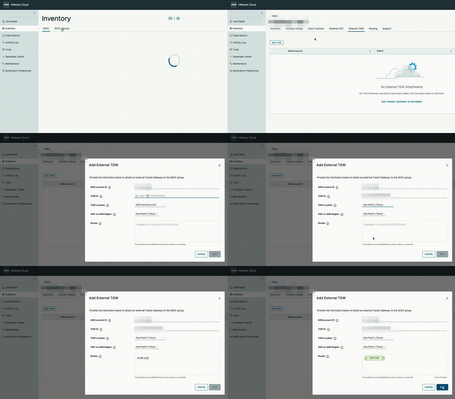
Unless already present, go to the AWS console and deploy a Transit Gateway (TGW) in the same region as VMC. Then, in the VMware Cloud on AWS management console, go to “SDDC groups” and deploy a new VTGW. Once deployed, navigate to the “External TGW” tab, click “Add TGW” and enter the account number and the ID of the customer TGW to connect to as well as the regions to use.

In the “Routes” box, enter the CIDR range of the VPC which NC2 is to be deployed into. In this example, “10.90.0.0/16”.

This will advertise the NC2 VPC CIDR to VMware Cloud on AWS and also create a peering attachment invitation from the VMware AWS account to the customer AWS account.

Method 2: Steps to deploy: Configure the TGW

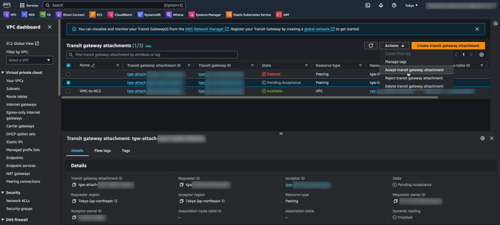
The invitation to add the peering attachment can be accepted through “Transit Gateway Attachments” in the AWS console in the customer account.

While here, take the opportunity to add an attachment to the VPC into which NC2 will be deployed.

Accepting the peering invitation in the AWS console

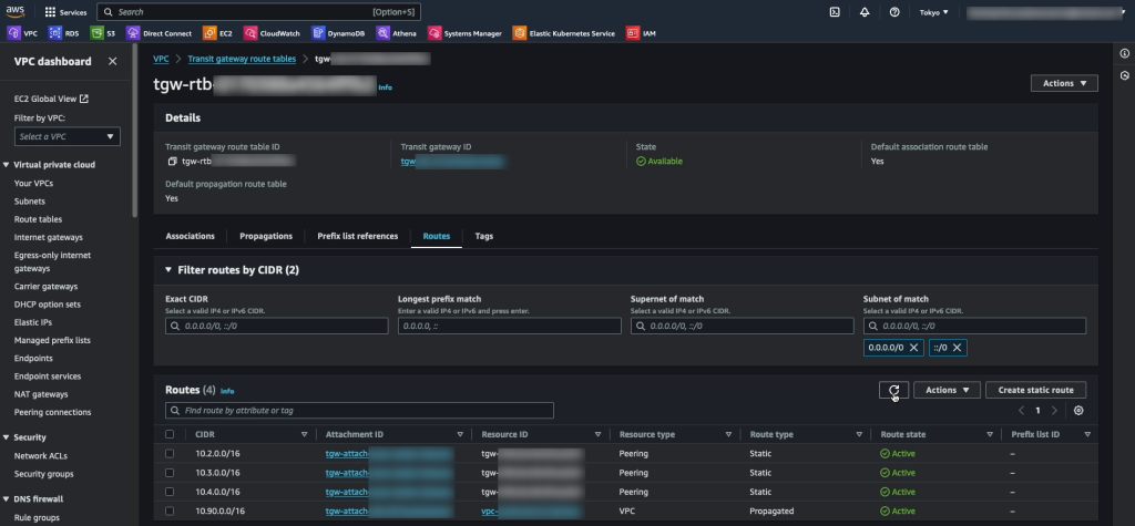
In the customer AWS account, navigate to the Transit Gateway route table section, select the route table for the TGW peered with VMC and add the routes for the VMC networks. In this case “10.2.0.0/16”, “10.3.0.0/16” and “10.4.0.0/16”. Note that these are added as Static routes.

In addition we have the “10.90.0.0/16” network added via the VPC attachment. There is no need to add static routes for this network as it is propagated automatically.

Method 2: Steps to deploy: Configure the routes to the VMC cluster in the NC2 VPC

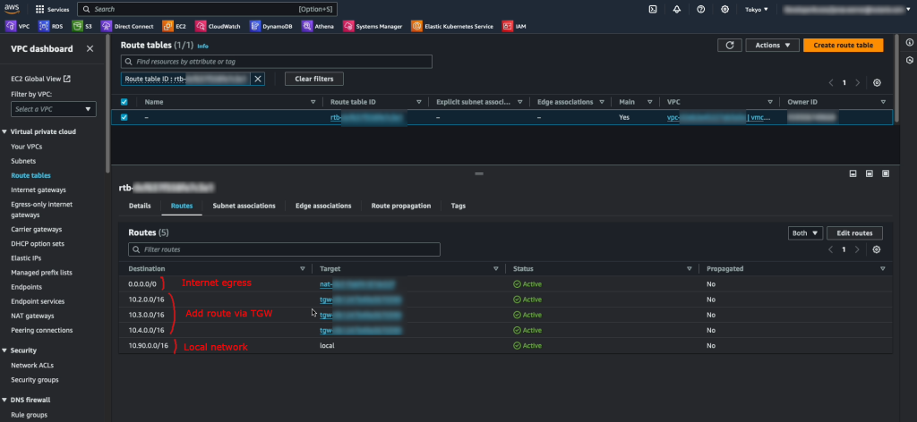
The final step for the routing is to add the routes for VMware Cloud on AWS into the route table(s) of the VPC which NC2 is to be deployed into. In our example, “10.2.0.0/16”, “10.3.0.0/16” and “10.4.0.0/16” are added as routes via the TGW attachment. “10.90.0.0/16” is our local network and there is a quad-zero route to the internet via a NAT GW.

This concludes the setup steps specific to Method 2. Please continue with the firewall settings, NC2 cluster deployment and Move installation below.

Firewall settings: Allow Move to access the VMC vCenter and ESXi hosts

Move requires access to the VMC vCenter instance and the ESXi hosts in order to migrate virtual machines. Through the VMware Cloud on AWS console, add a Management Gateway firewall rule to allow the NC2 VPC to access these resources.

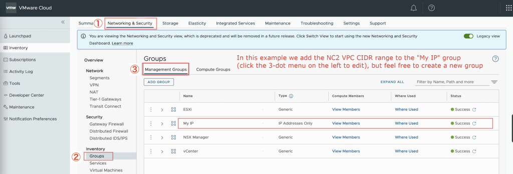
  • Add the NC2 VPC CIDR range to an MGW inventory group
    • Navigate to “Networking & Security”
    • Click “Groups” under “Inventory”
    • Click “Management Groups” to edit the groups pertaining to the MGW
    • Add or modify a group and add the CIDR range of the VPC which NC2 is deployed into
      • To modify an existing group, click the 3-dot menu on the left of the group and select “Edit”
Adding the NC2 VPC CIDR range to an MGW inventory group
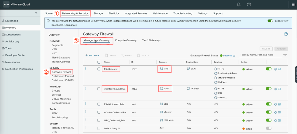
  • Add the MGW inventory group to the MGW firewall rules
    • Navigate to “Networking & Security”
    • Click “Gateway Firewall” under “Security”
    • Click “Management Gateway” to edit rules for the MGW
    • Update the rules for ESXi and vCenter by adding the MGW inventory group containing the NC2 VPC CIDR range with the action “Allow”
Adding the MGW inventory group to a MGW firewall rule allowing access to ESXi and vCenter from the NC2 VPC

Deploy the NC2 cluster

Sign up for NC2 or start a trial and deploy through the NC2 deployment wizard. Select the latest version – 6.8, to get Flow overlay networking and the centralized management through Prism Central included. When asked, select the VPC and the private subnets desired. In this case subnets in the “10.90.0.0/16” VPC.

After the NC2 cluster is deployed, deploy Move 5.3 on top of NC2 and register both the NC2 cluster and vCenter from the VMC environment.

Install Move and register NC2 and VMC

Download Move 5.3 from the download page: https://portal.nutanix.com/page/downloads?product=move

Follow the Move manual to deploy Move 5.3 on the NC2 cluster in AWS: https://portal.nutanix.com/page/documents/list?type=software&filterKey=software&filterVal=Move

VDDK upload: After Move is deployed, add the NC2 and VMC environments. After adding the VMC environment it will prompt for a VDDK file. This file can be downloaded from the VMware support site. The version used in this example is: “VMware-vix-disklib-7.0.3-19513565.x86_64”. Please use the Linux version.

Migrate the VMs to NC2

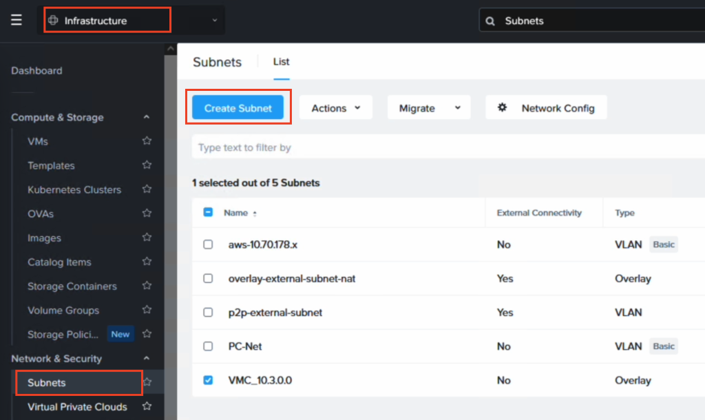
If IP retention is desired, use Flow in Prism Central to create an overlay VPC and subnet which matches the CIDR range of the NSX-T subnet in VMC from which the VMs will be migrated. In this example “10.3.0.0/24” is used.

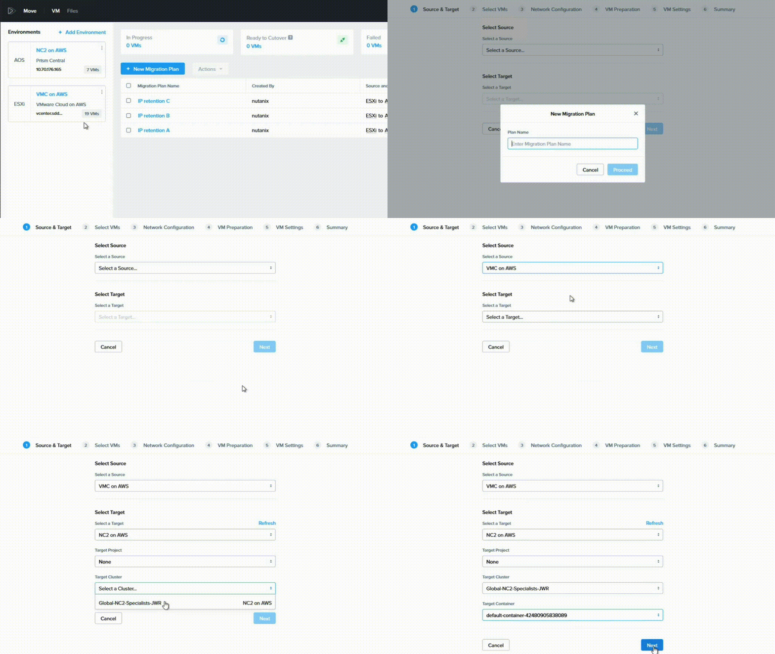
Now the only thing remaining is to create a Migration Plan in Move where VMC is the source and NC2 is the target. Ensure to select the correct target network to ensure IP retention works as expected.

Wrap up

This has been an example of the steps required for migrating Virtual Machines from VMware Cloud on AWS (VMC) to Nutanix Cloud Clusters (NC2) without changing the IP or MAC addresses of the migrated VMs. For more information or for a demo, please reach out to your Nutanix representative or partner.

Additional resources

Migrating VMs from on-premises vSphere to VMware Cloud on AWS using NetApp SnapMirror

Note: This blog post is part of the 2022 edition of the vExpert Japan Advent Calendar series for the 9th of December.

Migration from an on-premises environment to VMware Cloud on AWS can be done in a variety of ways. The most commonly used (and also recommended) method is Hybrid Cloud Extensions – HCX. However, if VMs are stored on a NetApp ONTAP appliance in the on-prem environment, the volume the VMs reside on can easily be copied to the cloud using SnapMirror. Once copied, the volume can be mounted to VMware Cloud on AWS and the VMs imported. This may be a useful method of migration provided some downtime is acceptable.

Tip: If you are just testing things out, NetApp offers a downloadable virtual ONTAP appliance which can be deployed with all features enabled for 60 days.

Prerequisites

  • Since SnapMirror is a licensed feature, please make sure a license is available on the on-prem environment. FSx for NetApp ONTAP includes SnapMirror functionality
  • SnapMirror only works between a limited range of ONTAP versions. Verify that the on-prem array is compatible with FSxN. The version of FSxN at the time of writing is “NetApp Release 9.11.1P3”. Verify your version (“version” command from CLI) and compare with the list for “SnapMirror DR relationships” provided by NetApp here: https://docs.netapp.com/us-en/ontap/data-protection/compatible-ontap-versions-snapmirror-concept.html#snapmirror-synchronous-relationships
  • Ensure the FSxN ENIs have a security group assigned allowing ICMP and TCP (in and outbound) on ports 11104 and 11105

Outline of steps

  1. Create an FSx for NetApp ONTAP (FSxN) file system
  2. Create a target volume in FSxN
  3. Set up cluster peering between on-prem ONTAP and FSxN
  4. Set up Storage VM (SVM) peering between on-prem ONTAP and FSxN
  5. Configure SnapMirror and Initialize the data sync
  6. Break the mirror (we’ll show deal with the 7 years of bad luck in a future blog post)
  7. Add an NFS mount point for the FSxN volume
  8. Mount the volume on VMware Cloud on AWS
  9. Import the VMs into vCenter
  10. Configure network for the VMs

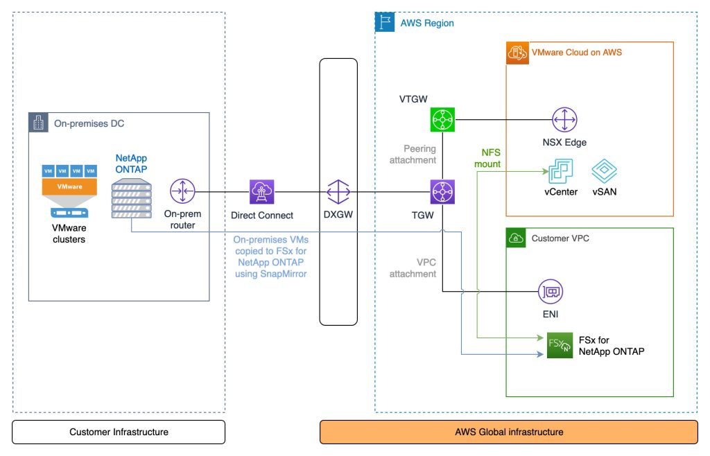
Architecture diagram

The peering relationship between NetApp ONTAP on-prem and in FSxN requires private connectivity. The diagram shows Direct Connect, but a VPN terminating at the TGW can also be used

Video of the process

This video shows all the steps outlined previously with the exception of creating the FSxN file system – although that is a very simple process and hardly worth covering in detail regardless

Commands

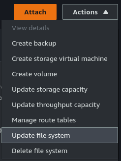
Open SSH sessions to both the on-premises ONTAP array and FSxN. The FSxN username will be “fsxadmin”. If not known, the password can be (re)set through the “Actions” menu under “Update file system” after selecting the FSxN file system in the AWS Console.

Step 1: [FSxN] Create the file system in AWS

The steps for this are straight-forward and already covered in detail here: https://docs.aws.amazon.com/fsx/latest/ONTAPGuide/getting-started-step1.html

Step 2: [FSxN] Create the target volume

Note that the volume is listed as “DP” for Data Protection. This is required for SnapMirror.

FsxId0e4a2ca9c02326f50::> vol create -vserver svm-fsxn-multi-az-2 -volume snapmirrorDest -aggregate aggr1 -size 200g -type DP -tiering-policy all
[Job 1097] Job succeeded: Successful

FsxId0e4a2ca9c02326f50::>
FsxId0e4a2ca9c02326f50::> vol show
Vserver   Volume       Aggregate    State      Type       Size  Available Used%
--------- ------------ ------------ ---------- ---- ---------- ---------- -----

svm-fsxn-multi-az-2
          onprem_vm_volume_clone
                       aggr1        online     RW         40GB    36.64GB    3%
svm-fsxn-multi-az-2
          snapmirrorDest
                       aggr1        online     DP        200GB    200.0GB    0%
svm-fsxn-multi-az-2
          svm_fsxn_multi_az_2_root
                       aggr1        online     RW          1GB    972.1MB    0%
8 entries were displayed.

FsxId0e4a2ca9c02326f50::>

Step 3a: [On-prem] Create the cluster peering relationship

Get the intercluster IP addresses from the on-prem environment

JWR-ONTAP::> network interface show -role intercluster
            Logical    Status     Network            Current       Current Is
Vserver     Interface  Admin/Oper Address/Mask       Node          Port    Home
----------- ---------- ---------- ------------------ ------------- ------- ----
JWR-ONTAP
            Intercluster-IF-1
                         up/up    10.70.1.121/24     JWR-ONTAP-01  e0a     true
            Intercluster-IF-2
                         up/up    10.70.1.122/24     JWR-ONTAP-01  e0b     true
2 entries were displayed.

Step 3b: [FSxN] Create the cluster peering relationship

FsxId0e4a2ca9c02326f50::> cluster peer create -address-family ipv4 -peer-addrs 10.70.1.121, 10.70.1.122

Notice: Use a generated passphrase or choose a passphrase of 8 or more characters. To ensure the authenticity of the peering relationship, use a phrase or sequence of characters that would be hard to guess.

Enter the passphrase:
Confirm the passphrase:

Notice: Now use the same passphrase in the "cluster peer create" command in the other cluster.

FsxId0e4a2ca9c02326f50::> cluster peer show
Peer Cluster Name         Cluster Serial Number Availability   Authentication
------------------------- --------------------- -------------- --------------
JWR-ONTAP                 1-80-000011           Available      ok

Step 3c: [FSxN] Create the cluster peering relationship

Get the intercluster IP addresses from the FSxN environment

FsxId0e4a2ca9c02326f50::> network interface show -role intercluster
            Logical    Status     Network            Current       Current Is
Vserver     Interface  Admin/Oper Address/Mask       Node          Port    Home
----------- ---------- ---------- ------------------ ------------- ------- ----
FsxId0e4a2ca9c02326f50
            inter_1      up/up    172.16.0.163/24    FsxId0e4a2ca9c02326f50-01
                                                                   e0e     true
            inter_2      up/up    172.16.1.169/24    FsxId0e4a2ca9c02326f50-02
                                                                   e0e     true
2 entries were displayed.

Step 3d: [On-prem] Create the cluster peering relationship

Use the same passphrase as when using the cluster peer create command on the FSxN side in Step 3b

JWR-ONTAP::> cluster peer create -address-family ipv4 -peer-addrs 172.16.0.163, 172.16.0.163

Step 4a: [FSxN] Create the Storage VM (SVM) peering relationship

FsxId0e4a2ca9c02326f50::> vserver peer create -vserver svm-fsxn-multi-az-2 -peer-vserver svm0 -peer-cluster JWR-ONTAP -applications snapmirror -local-name onprem

Info: [Job 145] 'vserver peer create' job queued

Step 4b: [On-prem] Create the Storage VM (SVM) peering relationship

After the peer accept command completes, verify the relationship using “vserver peer show-all”.

JWR-ONTAP::> vserver peer accept -vserver svm0 -peer-vserver svm-fsxn-multi-az-2 -local-name fsxn-peer

Step 5a: [FSxN] Create the SnapMirror relationship

FsxId0e4a2ca9c02326f50::> snapmirror create -source-path onprem:vmware -destination-path svm-fsxn-multi-az-2:snapmirrorDest -vserver svm-fsxn-multi-az-2 -throttle unlimited
Operation succeeded: snapmirror create for the relationship with destination "svm-fsxn-multi-az-2:snapmirrorDest".

FsxId0e4a2ca9c02326f50::> snapmirror show
                                                                       Progress
Source            Destination Mirror  Relationship   Total             Last
Path        Type  Path        State   Status         Progress  Healthy Updated
----------- ---- ------------ ------- -------------- --------- ------- --------
onprem:vmware
XDP  svm-fsxn-multi-az-2:snapmirrorDest
Uninitialized
Idle           -         true    -

Step 5b: [FSxN] Initialize the SnapMirror relationship

This will start the data copy from on-prem to AWS

FsxId0e4a2ca9c02326f50::> snapmirror initialize -destination-path svm-fsxn-multi-az-2:snapmirrorDest -source-path onprem:vmware
Operation is queued: snapmirror initialize of destination "svm-fsxn-multi-az-2:snapmirrorDest".

FsxId0e4a2ca9c02326f50::> snapmirror show
                                                                     Progress
Source            Destination Mirror  Relationship   Total             Last
Path        Type  Path        State   Status         Progress  Healthy Updated
----------- ---- ------------ ------- -------------- --------- ------- --------
onprem:vmware
          XDP  svm-fsxn-multi-az-2:snapmirrorDest
                            Uninitialized
                                    Transferring   0B        true    09/20 08:55:05

FsxId0e4a2ca9c02326f50::> snapmirror show
                                                                     Progress
Source            Destination Mirror  Relationship   Total             Last
Path        Type  Path        State   Status         Progress  Healthy Updated
----------- ---- ------------ ------- -------------- --------- ------- --------
onprem:vmware
          XDP  svm-fsxn-multi-az-2:snapmirrorDest
                            Snapmirrored
                                    Finalizing     0B        true    09/20 08:58:46

FsxId0e4a2ca9c02326f50::> snapmirror show
                                                                     Progress
Source            Destination Mirror  Relationship   Total             Last
Path        Type  Path        State   Status         Progress  Healthy Updated
----------- ---- ------------ ------- -------------- --------- ------- --------
onprem:vmware
          XDP  svm-fsxn-multi-az-2:snapmirrorDest
                            Snapmirrored
                                    Idle           -         true    -

FsxId0e4a2ca9c02326f50::>

Step 6: [FSxN] Break the mirror

FsxId0e4a2ca9c02326f50::> snapmirror break -destination-path svm-fsxn-multi-az-2:snapmirrorDest
Operation succeeded: snapmirror break for destination "svm-fsxn-multi-az-2:snapmirrorDest".

Step 7: [FSxN] Add an NFS mount point for the FSxN volume

FsxId0e4a2ca9c02326f50::> volume mount -volume snapmirrorDest -junction-path /fsxn-snapmirror-volume

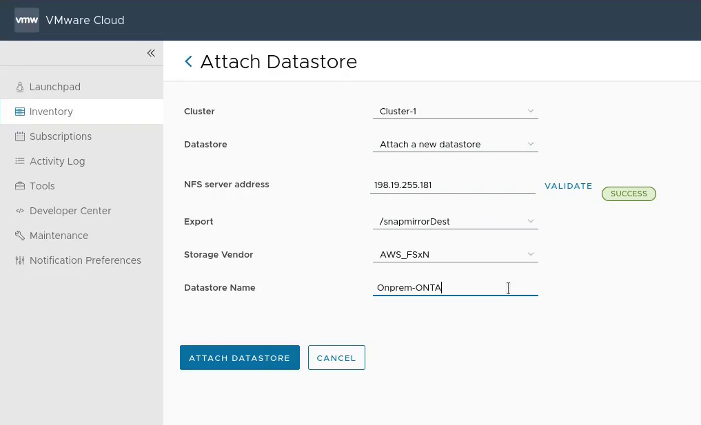
Step 8: [VMC] Mount the FSxN volume in VMware Cloud on AWS

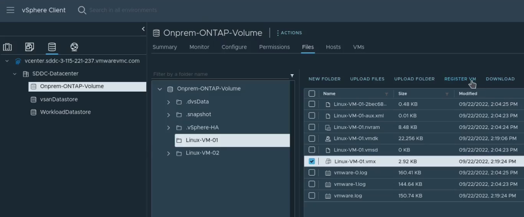
Step 9: [VMC] Import the VMs into vCenter in VMware Cloud on AWS

This can be done manually as per the screenshot below, or automated with a script

Manual import of VMs from the FSxN volume into VMware Cloud on AWS
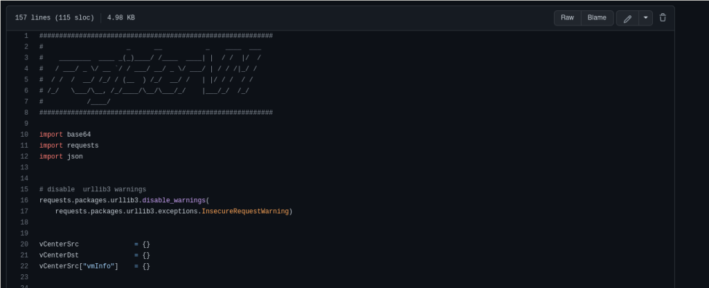
Importing using a Python script (initial release – may have rough edges): https://github.com/jonas-werner/vmware-vm-import-from-datastore/blob/main/registerVm.py

Video on how to use the script can be found here:

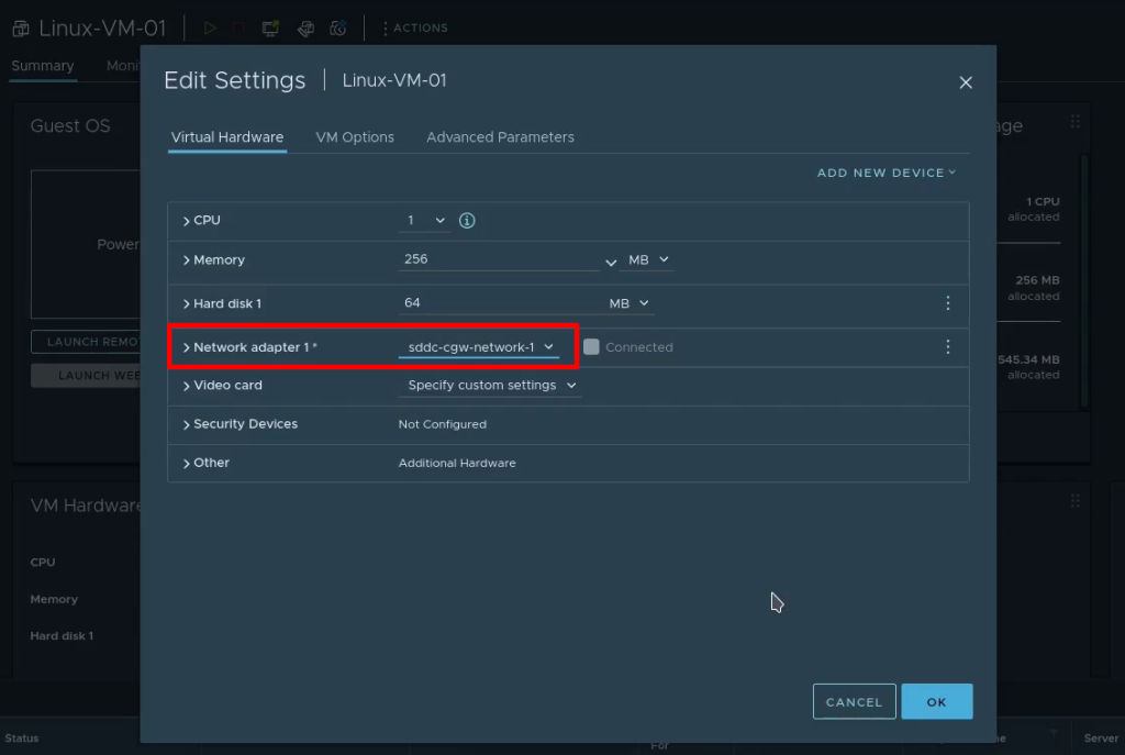
Step 10: [VMC] Configure the VM network prior to powering on

Wrap-up

That’s all there is to migrating VMs using SnapMirror between on-prem VMware and VMware Cloud on AWS environments. Hopefully this has been useful. Thank you for reading!

Migrate VMware VMs from an on-prem DC to VMware Cloud on AWS (VMC) using Veeam Backup and Replication

When migrating from an on-premises DC to VMware Cloud on AWS it is usually recommended to use Hybrid Cloud Extension (HCX) from VMware. However, in some cases the IT team managing the on-prem DC is already using Veeam for backup and want to use their solution also for the migration.

They may also prefer Veeam over HCX as HCX often requires professional services assistance for setup and migration planning. In addition, since HCX is primarily a tool for migrations, the customer is unlikely to have had experience setting it up in the past and while it is an excellent tool there is a learning curve to get started.

Migrating with Veeam vs. Migrating with HCX

Veeam Backup & RecoveryVMware Hybrid Cloud Extension (HCX)
Licensed (non-free) solutionFree with VMware Cloud on AWS
Arguably easy to set up and configureArguably challenging to set up and configure
Can do offline migrations of VMs, single or in bulkCan do online migrations (no downtime), offline migrations, bulk migrations and online migrations in bulk (RAV), etc.
Can not do L2 extensionCan do L2 extension of VLANs if they are connected to a vDS
Can be used for backup of VMs after they have been migratedIs primarily used for migration. Does not have backup functionality
Support for migrating from older on-prem vSphere environmentsAt time of writing, full support for on-prem vSphere 6.5 or newer. Limited support for vSphere 6.0 up to March 12th 2023

What we are building

This guide covers installing and configuring a single Veeam Backup and Recovery installation in the on-prem VMware environment and linking it to both vCenter on-prem as well as in VMware Cloud on AWS. Finally we do an offline migration of a VM to the cloud to prove it that it works.

Prerequisites

The guide assumes the following is already set up and available

  • On-premises vSphere environment with admin access (7.0 used in this example)
  • Windows Server VM to be used for Veeam install
    • Min spec here
    • Windows Server 2019 was used for this guide
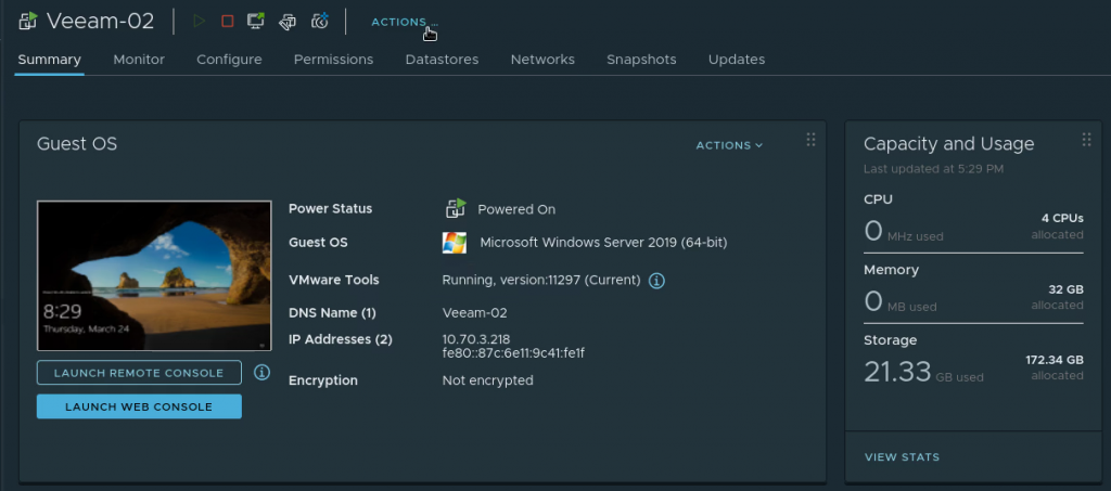
    • Note: I initially used 2 vCPU, 4GB RAM and 60 GB HDD for my Veeam VM but during the first migration the entire thing stalled and wouldn’t finish. After changing to 4 vCPU, 32Gb RAM and 170 GB HDD the migration finished quickly and with no errors. Recommend to assign as much resources as is practical to the Veeam VM to facilitate and speed up the migration
  • One VMware Cloud on AWS (VMC) Software Defined Datacenter (SDDC)
  • Private IP connectivity to the VMC SDDC
    • Use Direct Connect (DX) or VPN but it must be private IP connectivity or it won’t work
    • For this setup I used a VPN to a TGW, then a peering to a VMware Transit Connect (VTGW) which had an attachment to the SDDC, but any private connectivity setup will be OK
  • A test VM to use for migration

Downloading and installing Veeam

Unless you already have a licensed copy, sign up for a trial license and then download Veeam Backup and Recovery from here. Version 11.0.1.1216 used in this guide.

In your on-premises vSphere environment, create or select a Windows Server VM to use for the Veeam installation. The VM spec used for this install are as follows:

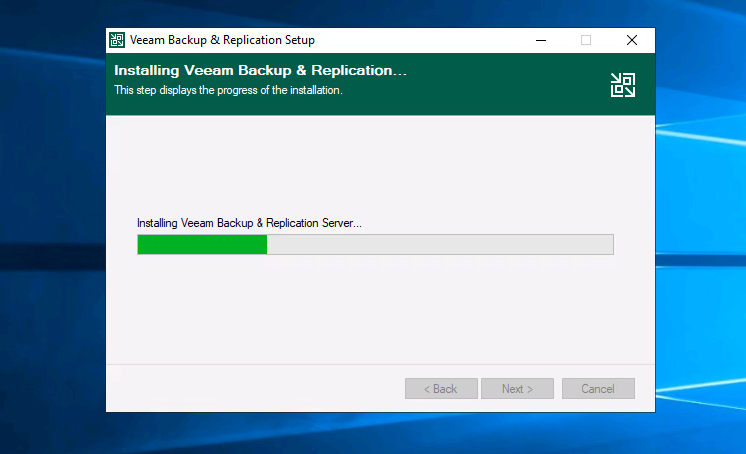
Run the install with default settings (next, next, next, etc.)

Register the on-prem vCenter in Veeam

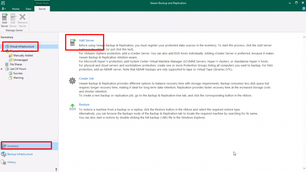
Navigate to “Inventory” at the bottom left, then “Virtual Infrastructure” and click “Add Server” to register the on-prem vCenter server
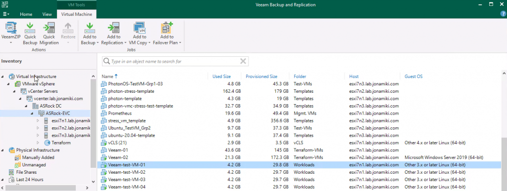
Listing VMs in the on-prem vSphere environment after the vCenter server has been registered in the Veeam Backup & Recovery console

Switching on-prem connectivity to VMware Cloud on AWS SDDC to use private IP addresses

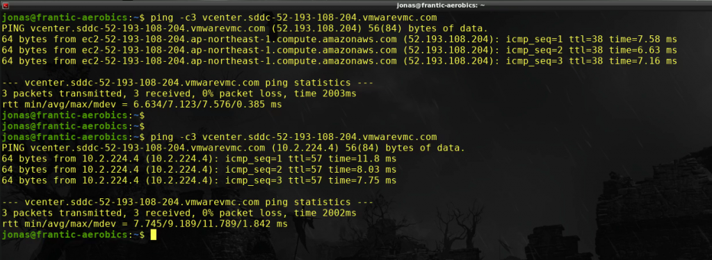
For this setup there is a VPN from the on-premises DC to the SDDC (via a TGW and VTGW in this case) but the SDDC FQDN is still configured to return the public IP address. Let’s verify by pinging the FQDN

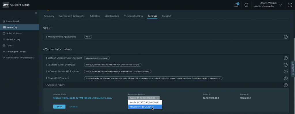
Switching the SDDC to return the private IP is easy. In the VMware Cloud on AWS web console, navigate to “Settings” and flip the IP to return from public to private

Ping the vCenter FQDN again to verify that private IP is returned by DNS and that we can ping it successfully over the VPN

All looks good. The private IP is returned. Time to register the VMware Cloud on AWS vCenter instance in the Veeam console

Registering the VMC vCenter instance with Veeam

Just use the same method as used when adding the on-premises vCenter server: Navigate to “Inventory” at the bottom left, then “Virtual Infrastructure” and click “Add Server” to register the on-prem vCenter server with Veeam
Note: If the SDDC vCenter had not been switched to use a private IP there will be an error in listing the data stores. Subsequently when migrating a VM the target data store won’t be listed and the migration can’t be started
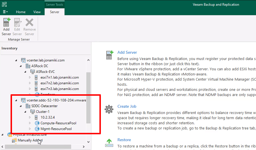
After adding the VMware Cloud on AWS SDDC vCenter the resource pools will be visible in the Veeam console

Now both vSphere environments are registered. Time to migrate a VM to the cloud!

Migrating a VM to VMware Cloud on AWS

Below is both a video and a series of screenshots describing the migration / replication job creation for the VM.

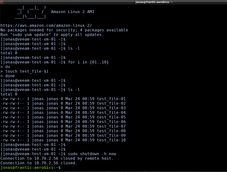
Creating some test files on the source VM to be migrated

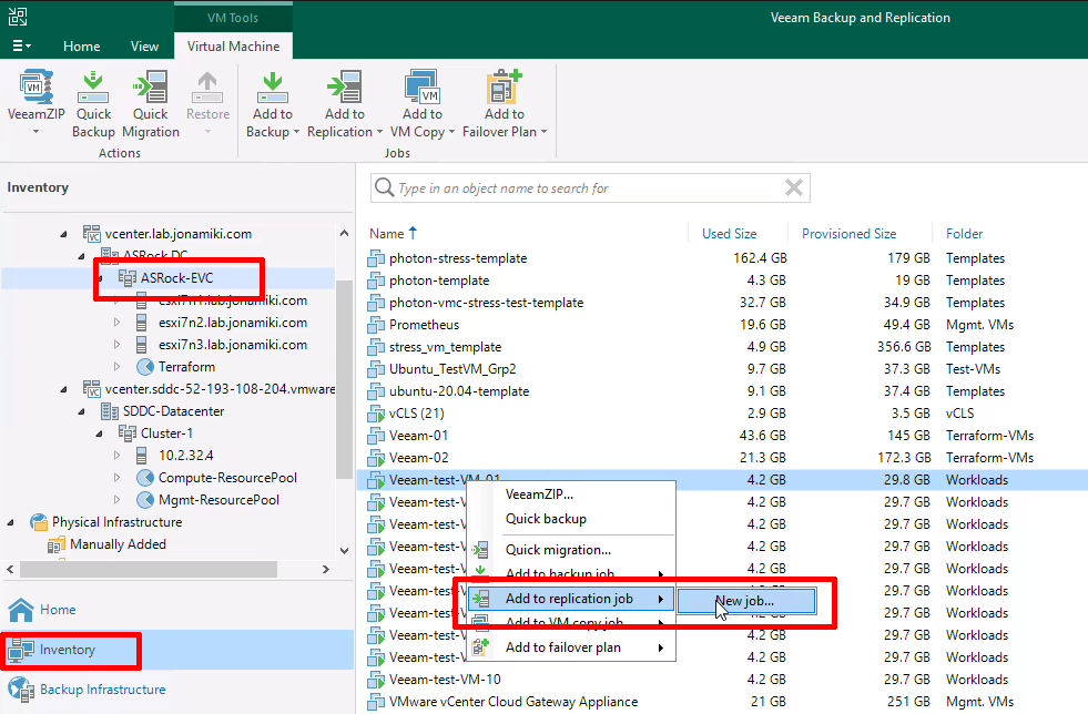
Navigate to “Inventory” using the bottom left menu, click the on-premises vCenter server / Cluster and locate a VM to migrate in the on-premises DC VM inventory. Right-click the VM to migrate and create a replication job

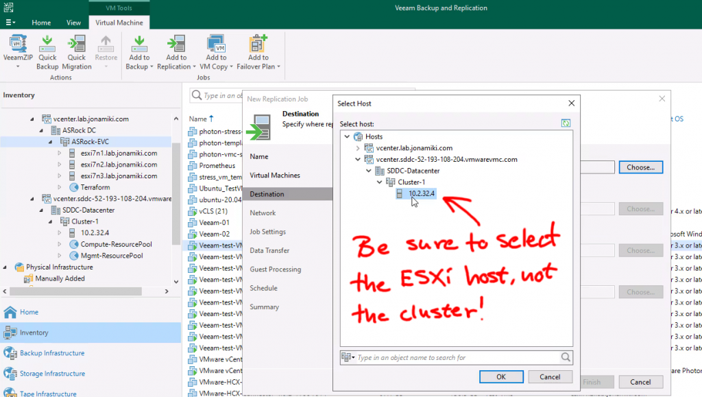
When selecting the target for the replication, be sure to expand the VMware cloud on AWS cluster and select one of the ESXi servers. Selecting the cluster is not enough to list up the required resources, like storage volumes

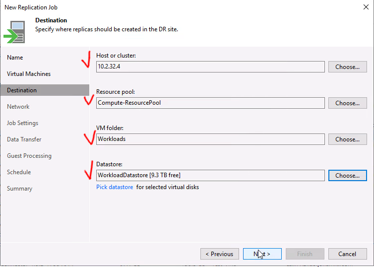
Since VMC is a managed environment we want to select the customer-side of the storage, folder and resource pools

If you checked the box for remapping the network is even possible to select a target VLAN for the VM to be connected to on the cloud side!

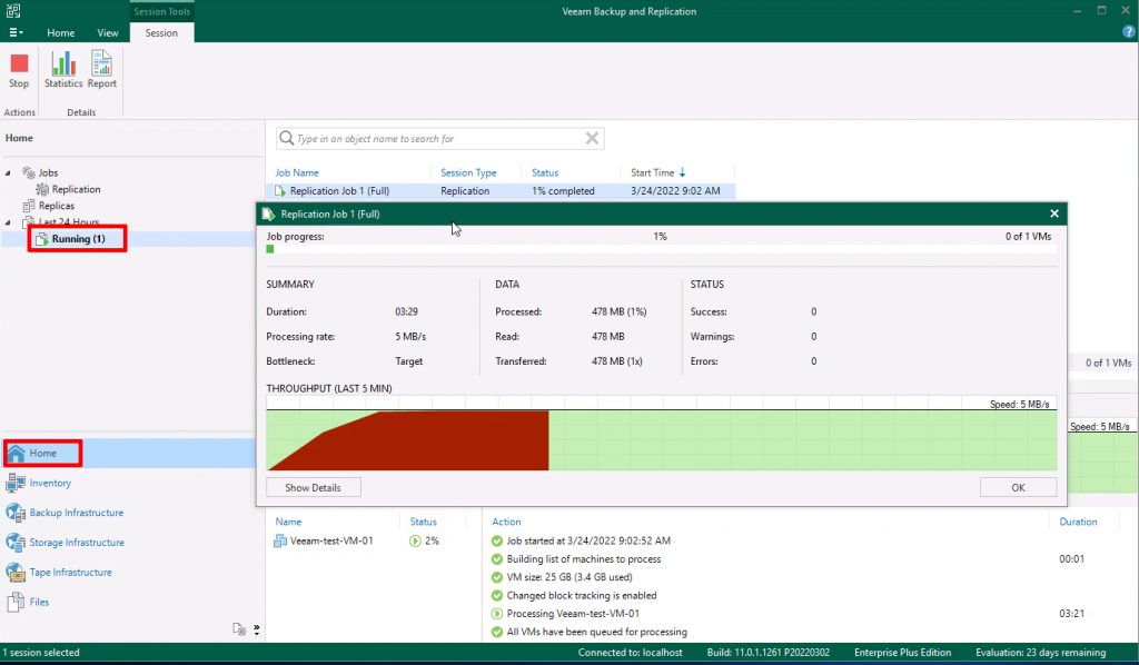
Select to start the “Run the job when I click finish” and move to the “Home” tab to view the “Running jobs”

The migration of the test VM finished in less than 9 minutes

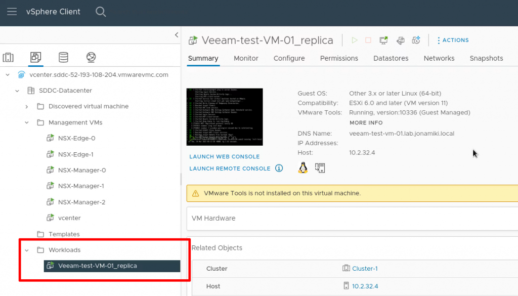
In the vCenter client for VMware Cloud on AWS we can verify that the replicated VM is present

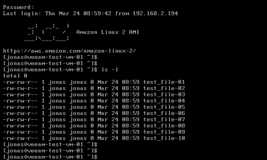
After logging in and listing the files we can verify that the VM is not only working but also have the test files present in the home directory

Thank you for reading! Hopefully this has provided an easy-to-understand summary of the steps required for a successful migration / replication of VMs to VMC using Veeam