
This guide covers NC2 concepts and demonstrates how to configure an Azure network environment for deploying Nutanix Cloud Clusters (NC2) on Azure. While NC2 can be deployed quickly and easily through the NC2 portal inclusive of the creation of required VNets, subnets, and other Azure resources—this method may impose limitations on post-deployment modifications.
For instance, if the VNets are created via the NC2 portal, it may not be possible to transition a non-redundant configuration into a redundant or scale-out configuration. To address this, this guide provides step-by-step instructions for manually creating the necessary Azure network resources. Additionally, it highlights key considerations to ensure a smooth and successful deployment process.
Single vs. Scale-out Flow Gateway (FGW)
North-South traffic flow for workloads / User VMs (UVMs) on NC2 on Azure goes via one or several Flow Gateway (FGW) VMs. Since all outbound UVM traffic goes through these VMs, please select the number required based on the throughput you need for the workloads on your NC2 cluster. There are two types of FGW which support 10Gbps and 16Gbps of throughput each respectively.
These FGW VMs are not deployed on NC2 on Azure. Instead they are deployed as Azure native VM instances. Each FGW connects to an External and Internal Azure subnet. The NC2 cluster is set to send all external-facing traffic over Equal-cost Multipath (ECMP) with these FGW VMs as the next hop.
These FGW’s can be deployed in single or scale-out mode. As would be expected, single implies the FGW is a single point of failure. However, the health of the FGW is continuously monitored by the NC2 portal and it will be re-provisioned in case it malfunctions.
For scale-out, or redundant mode, two, three or a max of four FGW VMs are deployed in an active/active formation where traffic can flow through any and all of the VMs.
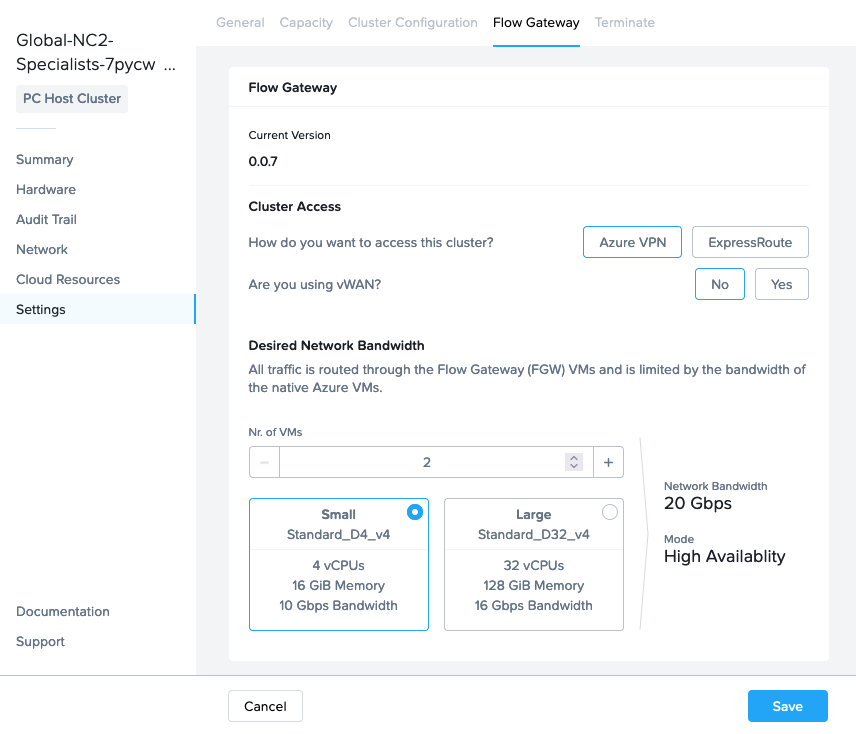
The above screenshot is from the NC2 portal where from the “Settings” menu we have highlighted the “Flow Gateway” tab to allow us to view and update FGW and other network related settings.
BGP speaker VMs
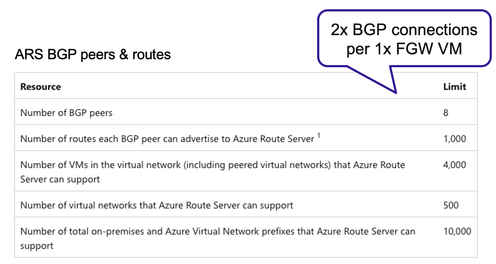
When scale-out FGW is selected, routing shifts from using static routes (UDR) to Border Gateway Protocol (BGP). Two BGP VMs will be automatically deployed if the FGW configuration changes from single to scale-out and those BGP VMs will need an Azure Route Server (ARS) to talk to.
Each FGW uses two BGP sessions on the ARS which the BGP VMs are paired with. Since the soft BGP session limit for ARS is 8, please ensure your ARS have sufficient sessions available when scaling out your FGW configuration.
Azure quotas
Prior to deploying it is good practice to verify that Azure subscription isn’t running out of the type of resources which will be required for the NC2 on Azure deployment. This includes the ARS BGP sessions mentioned in the section above as well as the FGW VM types, vCPU, memory and storage.
The small FGW VMs are of type Standard_D4v_4, the large FGW VMs are Standard_D32_v4 and the two BGP VMs are of type “Standard_D4_v4 type” (4 vCPUs and 16 GiB mem).
Quotas can be checked in the Azure console here: https://portal.azure.com/#view/Microsoft_Azure_Capacity/QuotaMenuBlade/~/myQuotas
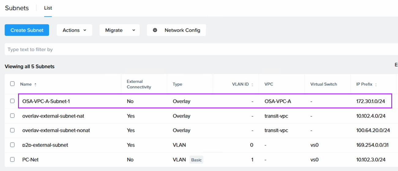
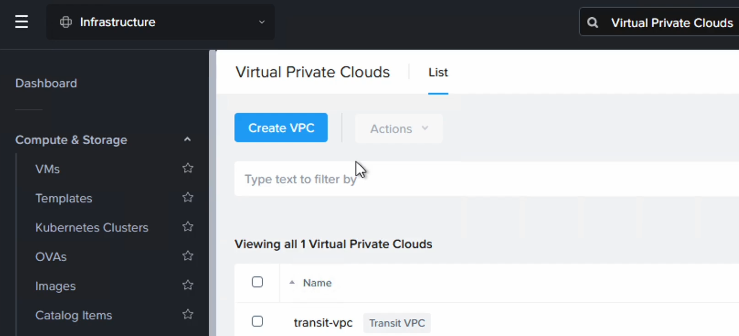
VNets and subnets
The bare minimum amount of VNet’s required to deploy NC2 on Azure is two, but you likely need more. For example, having a Hub VNet for routing traffic between on-prem and Azure as well as between VNet’s. We will look at two configurations in this post: ExpressRoute and S2S VPN. Note that all VNet’s need to be peered in a mesh fashion.
The VNet’s which are always required are the Cluster VNet for the bare metal cluster nodes on which NC2 is deployed as well as the Prism Central VNet which is used by the Prism Central management VM(s).
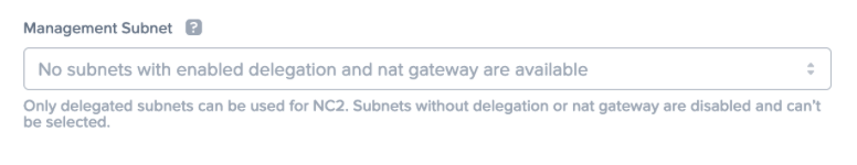
Both the bare-metal cluster nodes and the Prism Central management VM(s) require subnets delegated to the MS bare.metal service to function. Azure restricts the number of bare.metal subnets in a VNet to one. That forces us to create two VNet’s with a bare.metal delegated subnet each.
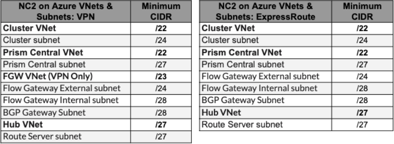
The FGW VMs need two subnets: One Internal for connecting to the NC2 network controller and one External for connecting to the outside world. Additionally, the BGP speaker VMs need a subnet for themselves too. That brings the number of subnets up to three. In an ExpressRoute environment these subnets can be co-hosted in the Prism Central VNet. However, in a S2S VPN environment we need to create a third VNet to host these resources. Let’s refer to the third VNet as the FGW VNet.
Please see the below CIDR ranges as guidance only. Always refer to the official documentation for the latest updates.
The NC2 portal will complain if required subnets aren’t available for deployment. In this example the VNet lacks a subnet delegated to the bare.metal service.
NAT Gateways
The NC2 cluster, FGW VMs and other resources need to be able to communicate with the NC2 portal as well as various other endpoints outside the NC2 environment. These are detailed in the prerequisites part of the user guide. NAT Gateways are required to provide that internet-facing access and the NC2 portal will check that these are present during deployment. Deploying NC2 without NAT Gateways is possible but necessitates reaching out to Nutanix support to disable the NC2 portal check prior to deploying. In that case internet access would need to be provided through a Network Virtual Appliance (NVA) and vWAN. Please refer to the NC2 on Azure networking best practices guide for more detail.
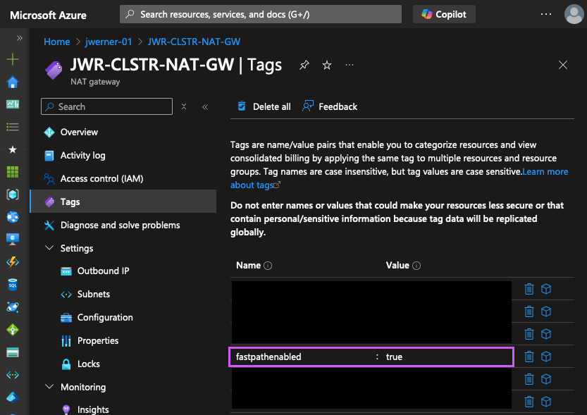
“fastpathenabled”: Note that at the time of writing (December 19th 2024) the NC2 portal requires every NAT Gateway used with NC2 to have the “fastpathenabled” tag set to “true” for deployment to proceed. The tag can be added to existing NAT Gateways and doesn’t have to be present at time of NAT GW creation.
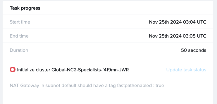
Below is an example of an error where one of the NAT Gateways used doesn’t have this tag configured.
Custom DNS server settings
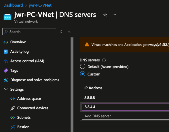
Prior to deploying, please update the DNS server settings on each VNet to be used with NC2 to replace the Default (Azure-provided) DNS with a custom DNS server. In this example we use the Google 8.8.8.8 and 8.8.4.4 servers, but other DNS resolvers can be used too, including private DNS servers – provided they can also resolve all required public endpoints. Note that deployments to VNets with the Default DNS server configured will fail.
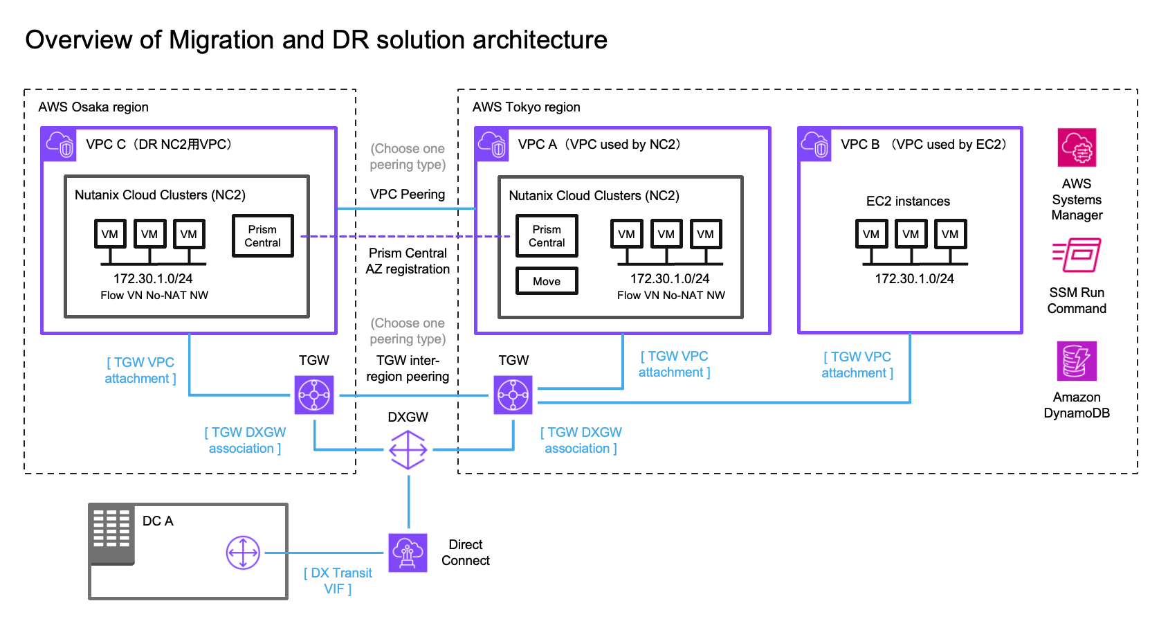
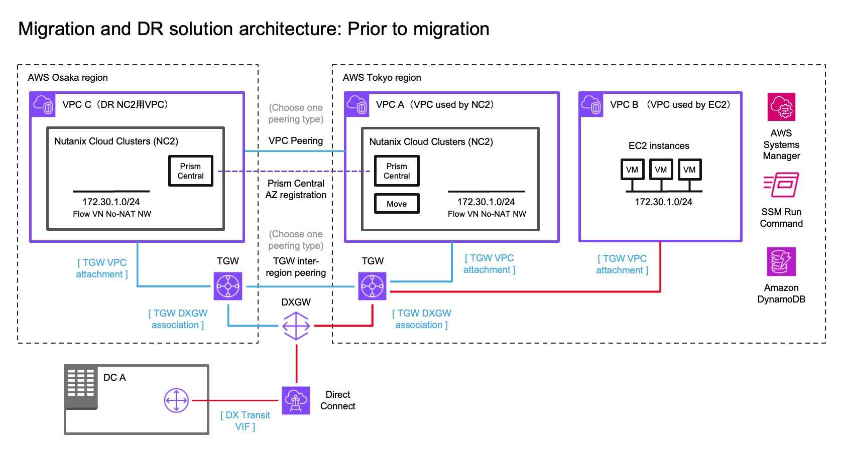
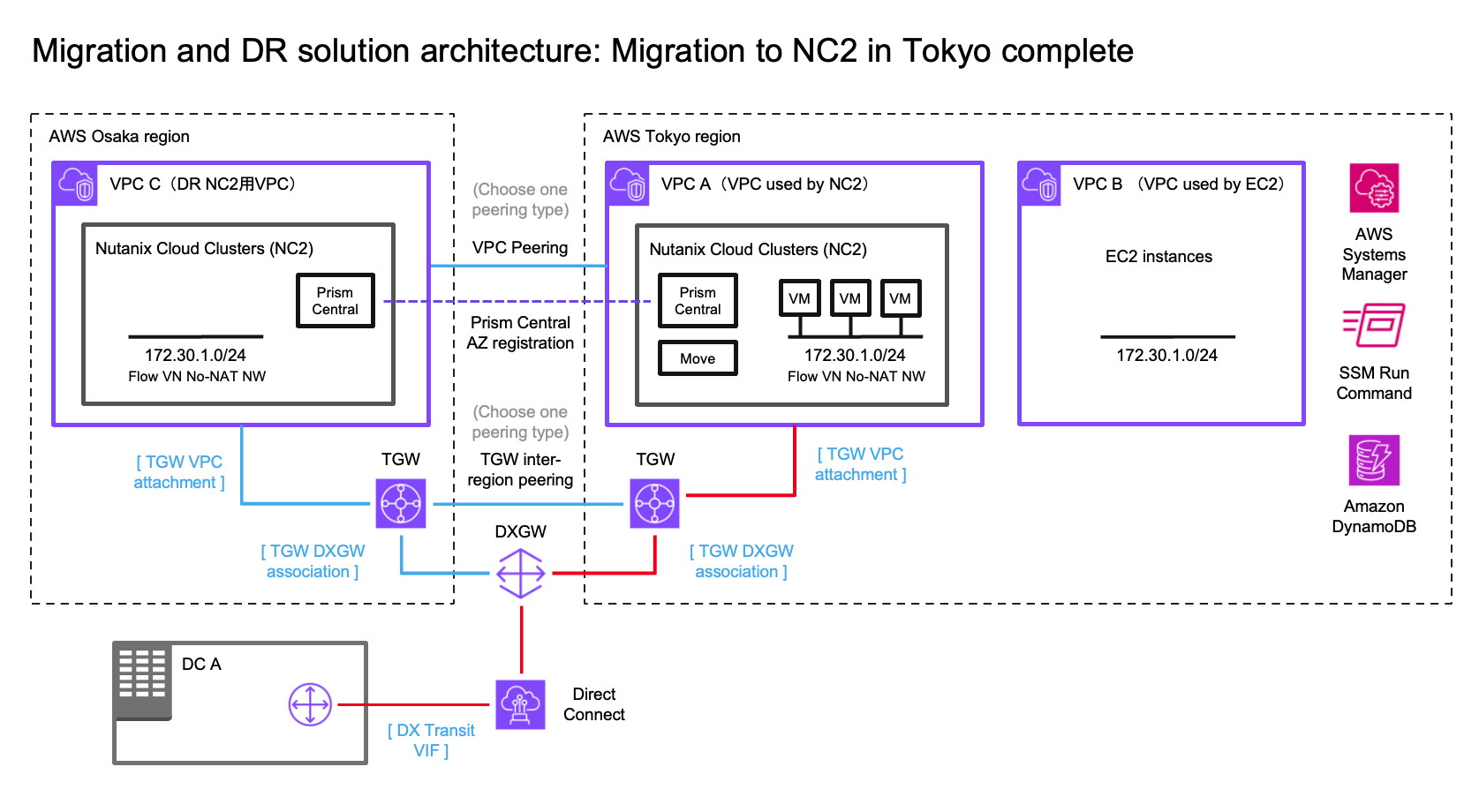
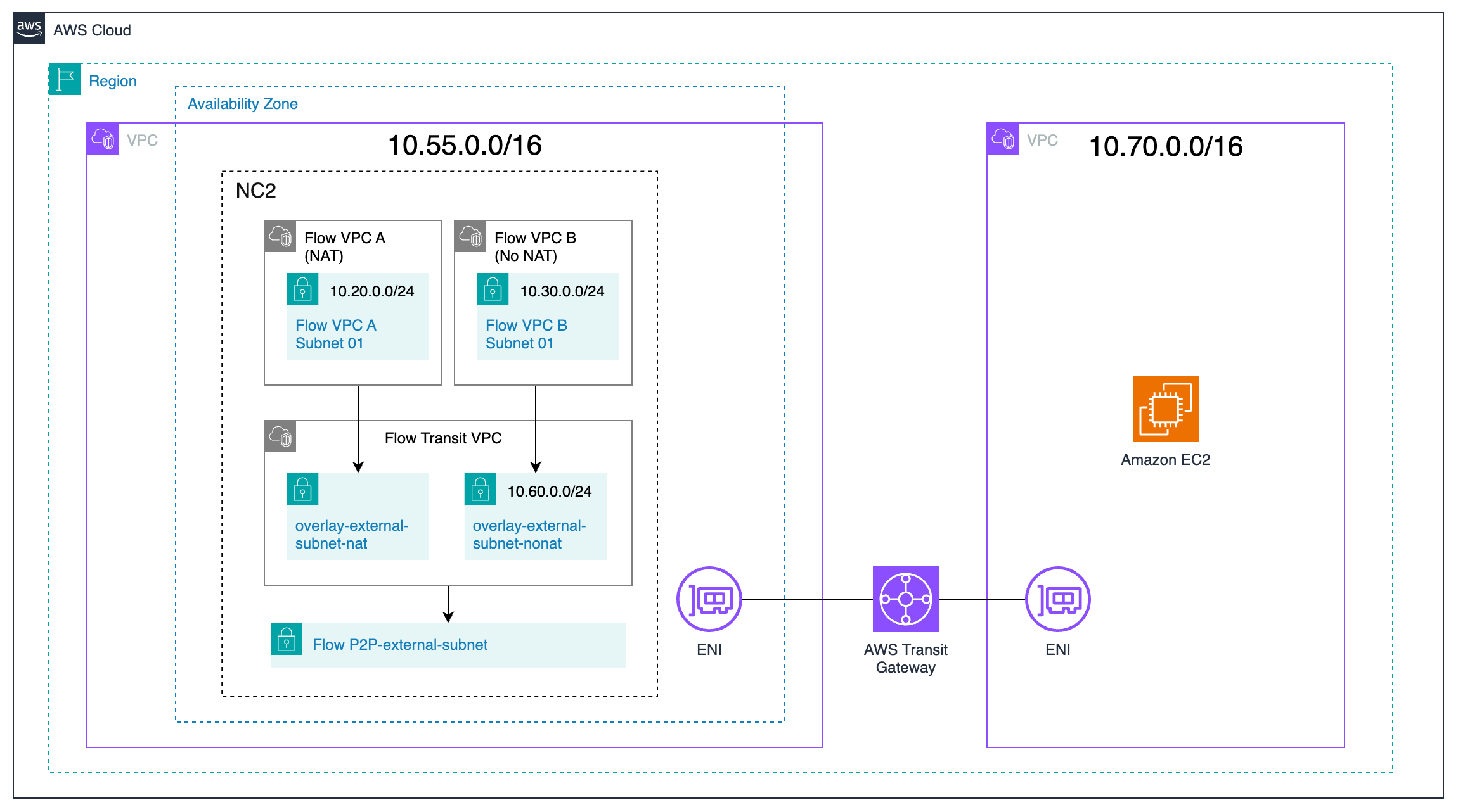
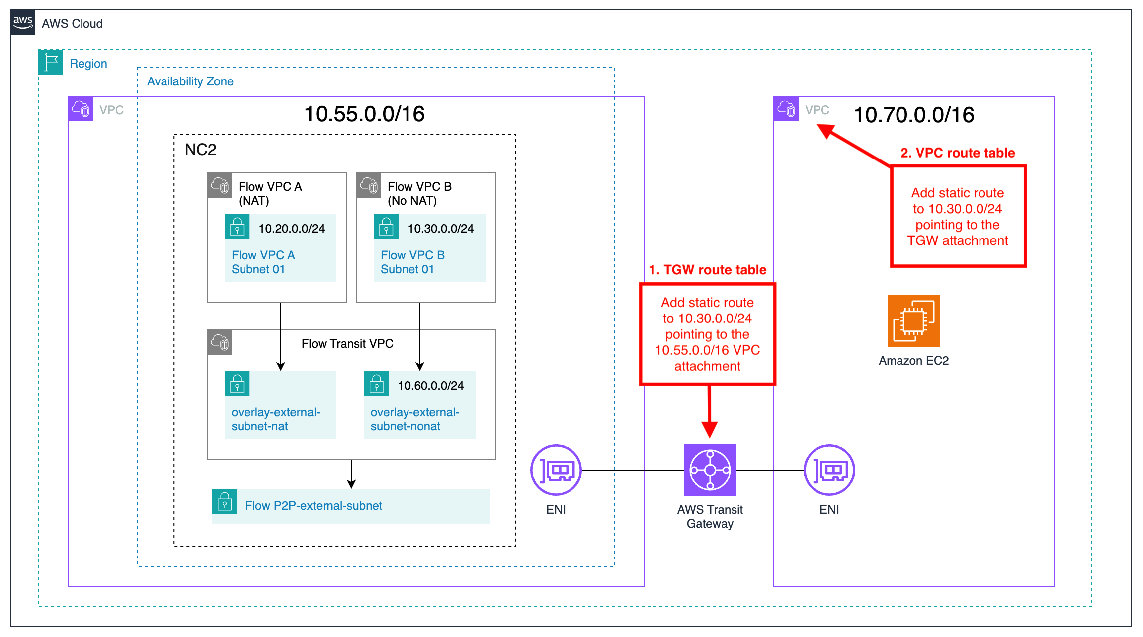
Solution architecture diagrams
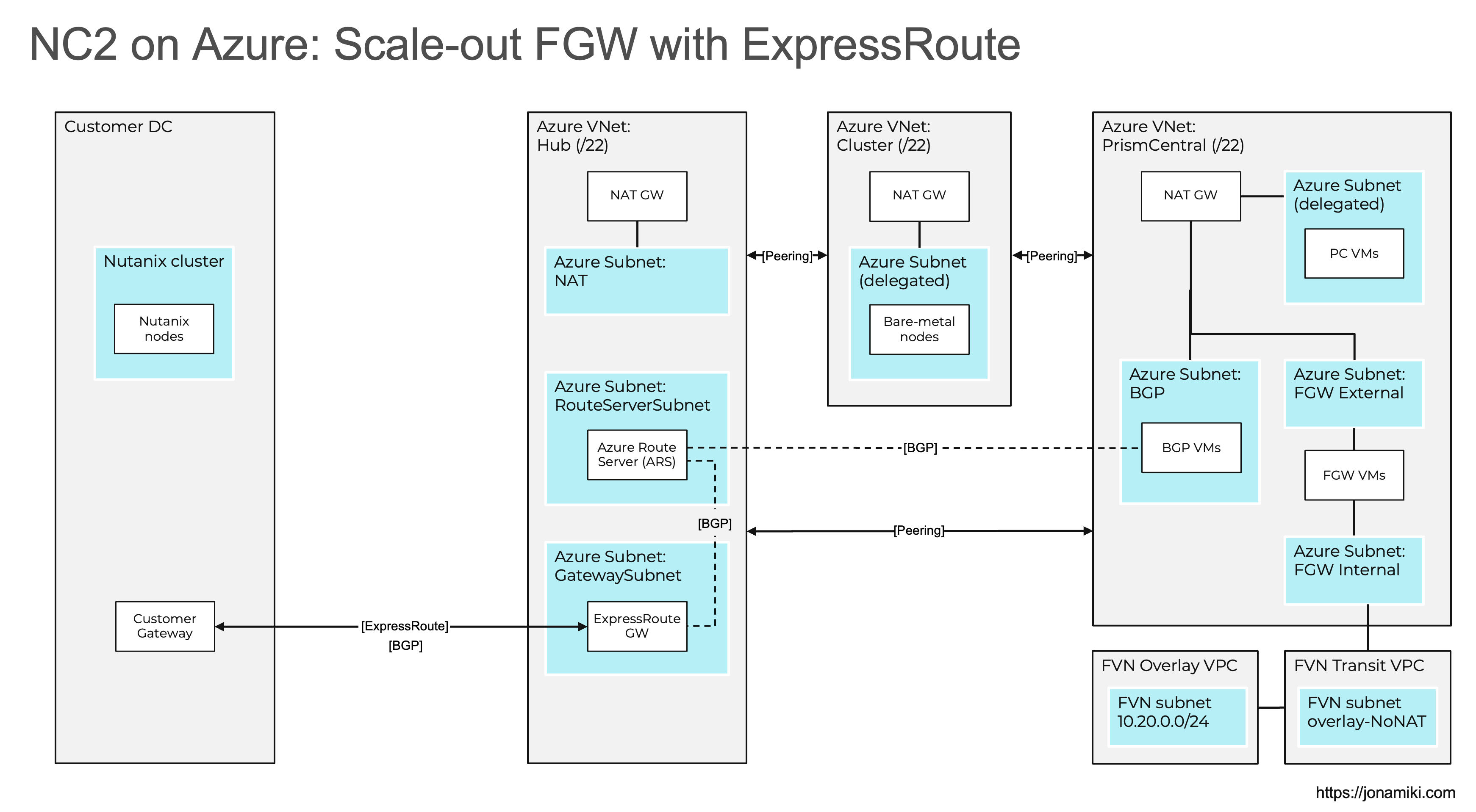
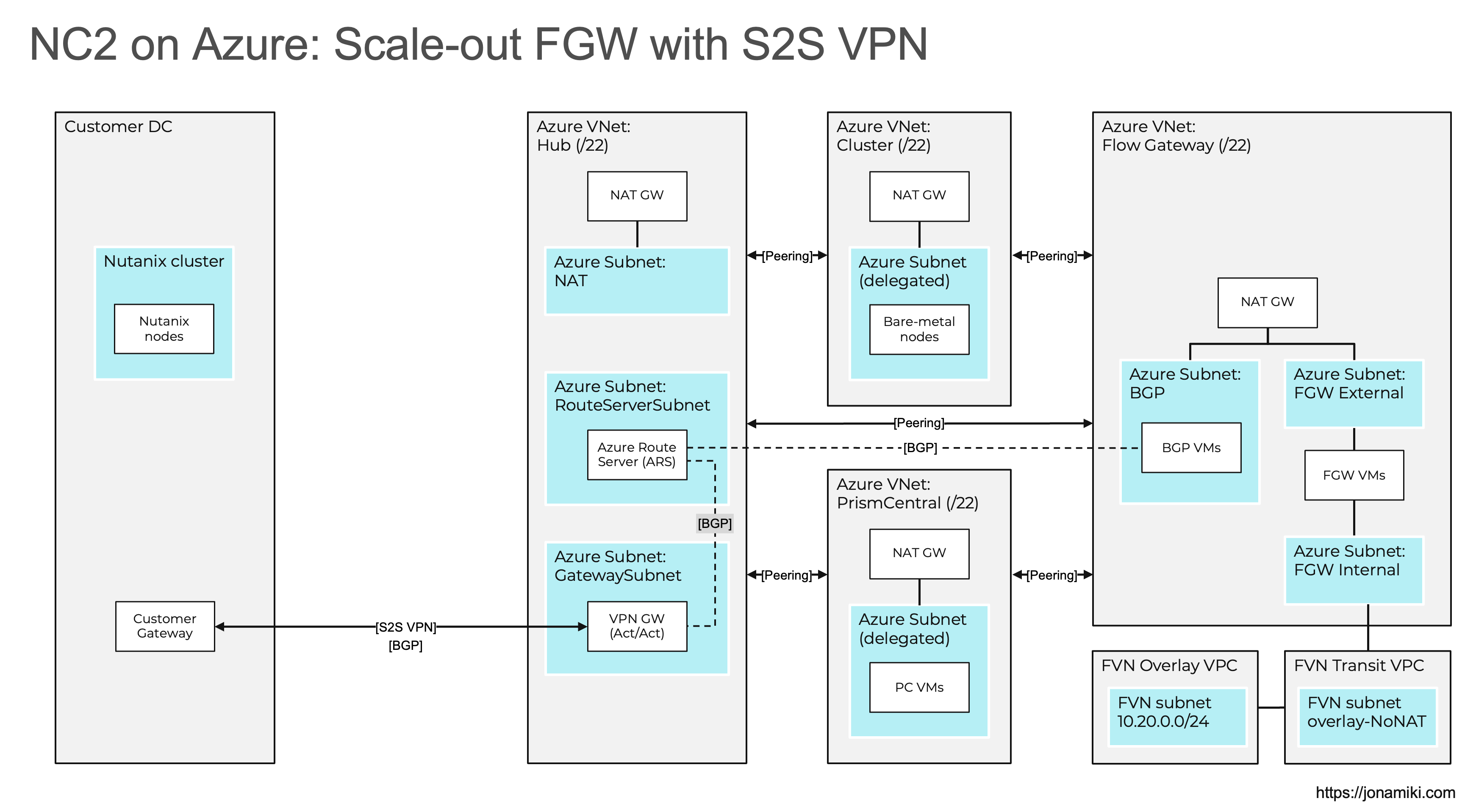
The Azure VNets are prefixed with “Azure” and on the bottom right there are two Flow Virtual Networking (FVN) VPCs prefixed with “FVN”. The FVN components are all created on top of the NC2 cluster and aren’t directly visible in the Azure management console. There are many more ways of configuring NC2 on Azure, but those are out of scope for this blog post. Please refer to the documentation for more detail.
ExpressRoute
As discussed above, the ExpressRoute option we have the benefit of co-hosting the FGW and BGP subnets in the Prism Central VNet.
Site-to-Site VPN
For the S2S VPN option we add the FGW VNet which will be used to host the FGW internal, external and the BGP subnets.
VNet peerings
When peering your VNets, please ensure to do a full mesh, as is show in the diagrams. In other words – Every VNet need to be peered with every other VNet.
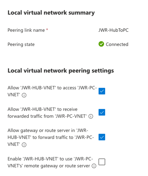
When peering from the Hub VNet, please use the following settings:
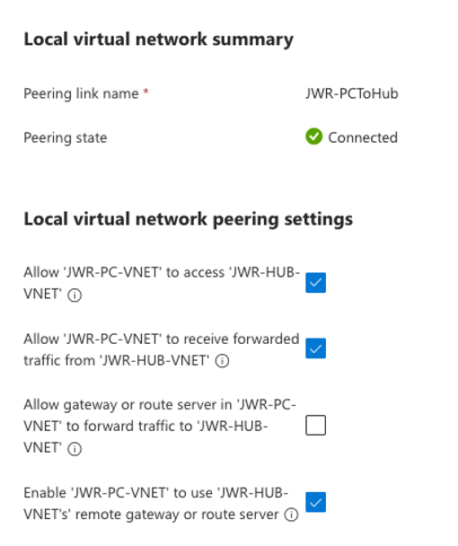
When peering from one of the other VNets (Cluster, Prism Central, FGW) to the Hub VNet, please use the following settings:
Summary and conclusion
In this blog post, we explored the foundational concepts of NC2 on Azure networking and presented solution architectures for two key use cases: ExpressRoute and Site-to-Site (S2S) VPN. We highlighted the required configurations, potential challenges, and important considerations.
By combining this guide with the official documentation, we aim to provide a clear path for manually creating Azure network infrastructure in preparation for an NC2 deployment.
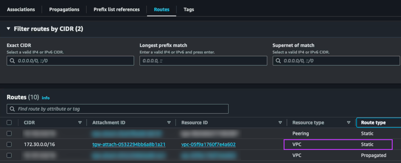
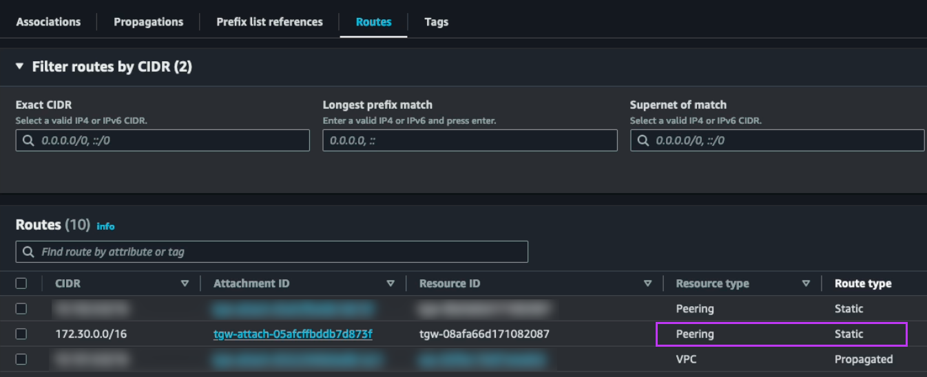
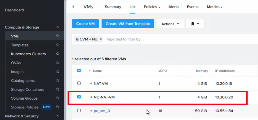
We hope you found this information helpful. In our next post, we will dive deeper into the BGP component and demonstrate how to route traffic for overlay no-NAT networks. Stay tuned!