Configuring AWS Systems Manager for use with VMware Cloud on AWS

Maintaining tight access control for workloads and ensuring they are on the latest patch revisions is central to running an efficient and secure IT environment. In this post we cover how to heighten security by leveraging the tools which comes with AWS Systems Manager and complementing AWS native services. This way IT administrators will be empowered with tools central to their quest of reaching higher security levels while simultaneously being able to reduce management overhead

This post is also available on AWS Re-post here: https://repost.aws/articles/ARRpq-n–pQSKwWteAIdpktw

Integrating AWS Systems Manager (SSM) with VMware Cloud on AWS

Deploying SSM can help enhance security for both cloud native and VMware Cloud on AWS environments. This post will show how to integrate SSM with VMware Cloud on AWS for secure remote access as well as security patching of VMs.

Detailed configuration steps are covered below, but the main points are:

  • Enabling and performing initial SSM configuration
  • Creating a VPC endpoint for SSM in the VMware Cloud on AWS connected VPC
  • Creating an inbound endpoint for Route 53
  • Install the SSM agent and registering the VMs with SSM

The SSM endpoint gives the VMs a private IP to communicate with SSM and the Route 53 inbound endpoint ensures that the VMs receive that private IP when they resolve the SSM FQDN. Without these two endpoints the VMs would communicate with SSM over the internet.

Architecture

Integrating AWS Systems Manager with VMware Cloud on AWS is relatively straightforward. While AWS SSM comes with public endpoints for VM-to-SSM communication, the preferred way is to use private IP addressing over the connected VPC Elastic Network Interface (ENI). To accomplish this, create an SSM endpoint in the connected VPC and then set the networks on the VMware Cloud on AWS SDDC CGW to use a Route 53 inbound resolver. That way any communication the SSM agent does to the regional SSM endpoint will go over the ENI rather than the internet. No changes on the VMs are required apart from ensuring they use the correct Route 53 DNS resolver.

Overall network architecture for AWS Systems Manager integration with VMware Cloud on AWS

Integrating AWS Systems Manager for the VMware Cloud on AWS environment involves creating an SSM endpoint in the customer connected VPC and adding a DNS inbound endpoint
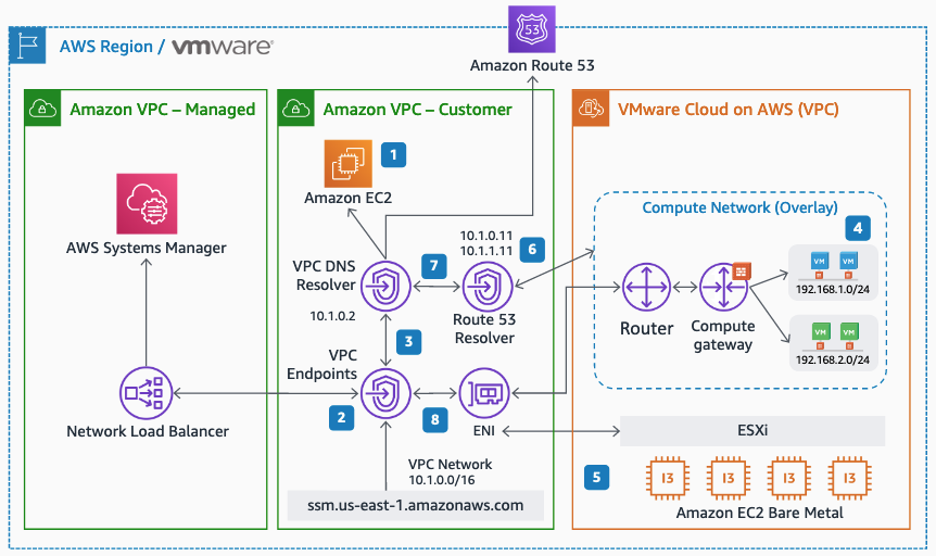
Full diagram: https://d1.awsstatic.com/architecture-diagrams/ArchitectureDiagrams/vmware-hybrid-cloud-mgmt-aws-systems-manager.pdf?did=wp_card&trk=wp_card

Configuration steps

In this section the practical setup of AWS Systems Manager with VMware Cloud on AWS is covered. General guidelines for getting started with AWS Systems Manager is covered in the SSM User Guide. The steps below are VMware and VMware Cloud on AWS specific and aim to get an environment up and running swiftly.

Overview of steps involved in setting up Systems Manager for use with VMware Cloud on AWS

  1. Setting the systems manager region
  2. Creating an S3 bucket for SSM logs and inventory output
  3. Creating the S3 bucket policy in IAM
  4. Creating the systems manager IAM users
  5. Creating the systems manager VPC endpoints
  6. Creating the R53 DNS inbound endpoint
  7. Pointing CGW DNS to R53
  8. Creating the SDDC firewall rules
  9. Creating a hybrid activation
  10. VM configuration: Installing the SSM agent and registering with SSM

1. Setting the systems manager region and enable Advanced-Tier

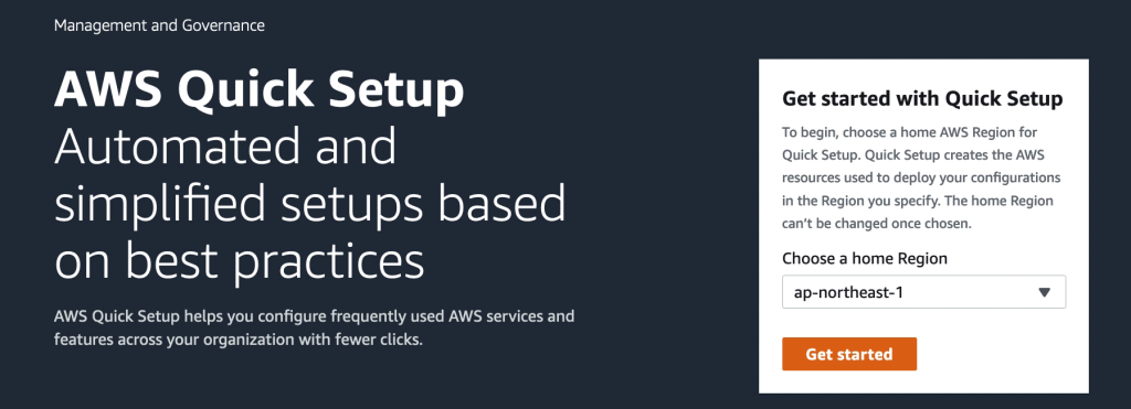
AWS Systems Manager is bound to a region of choice when activated the first time. Please pick a region which makes sense to your organization and note that it cannot be changed afterwards. For a VMware Cloud on AWS environment this would usually be the same region as the VMware Cloud on AWS environment is deployed in.

The easiest way to set the region is to go to AWS Systems Manager Quick Start and select your preferred region during the setup. Access AWS Systems Manager Console here: https://console.aws.amazon.com/systems-manager/ Also refer to the AWS Systems Manager getting started guide here: https://docs.aws.amazon.com/systems-manager/latest/userguide/quick-setup-getting-started.html
To use advanced features of AWS SSM, like patch management of VMware VMs, Advanced-Tier has to be enabled. This will incur an extra charge for instance management. At the time of writing the daily cost for one instance would be $0.1668 USD. Please refer to the SSM pricing structure for more detail and up-to-date pricing.

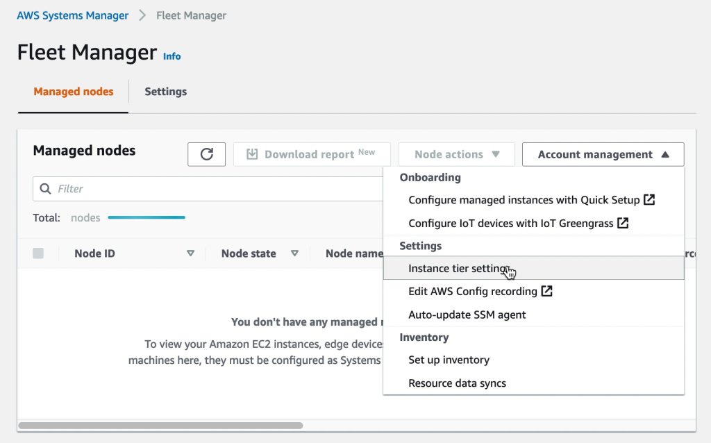
Once AWS SSM has been set to your preferred region, access “Fleet Manager” and under “Account management” select to modify the settings for Instance tiers.
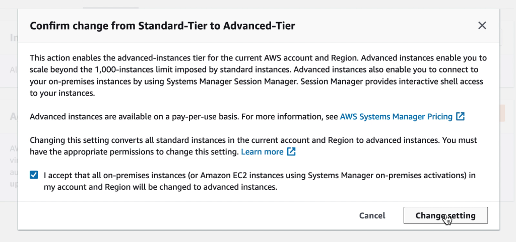
Under the “Instance tier settings” confirm change from Standard-Tier to Advanced-Tier
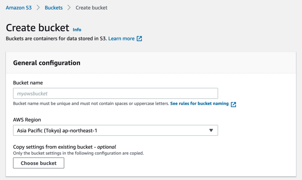
2. Creating an S3 bucket for SSM logs and inventory output

Having a designated S3 bucket for SSM logs and other output, like inventory data, makes administration easier. The output can later be accessed for tracking, troubleshooting or even for access via Athena where inventory data can be formatted using SQL queries and used in QuickSight reports.
3. Creating the S3 bucket policy in IAM

The S3 bucket created in step 2 need a policy to allow SSM to access it. This policy will be created in IAM and then attached to the IAM roles used in both cloud native and VMware Cloud on AWS environments. Note that while this is a policy for S3 access, it is created in IAM and not in the S3 console.
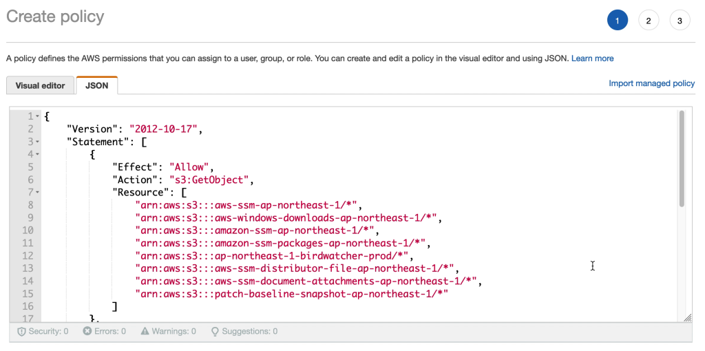
The policy is created based on the JSON document below. Please update “YOUR-REGION” and “YOUR-BUCKET-NAME” with the relevant values for your environment.

{
    "Version": "2012-10-17",
    "Statement": [
        {
            "Effect": "Allow",
            "Action": "s3:GetObject",
            "Resource": [
                "arn:aws:s3:::aws-ssm-YOUR-REGION/",
                 "arn:aws:s3:::aws-windows-downloads-YOUR-REGION/",
                "arn:aws:s3:::amazon-ssm-YOUR-REGION/",
                "arn:aws:s3:::amazon-ssm-packages-YOUR-REGION/",
                "arn:aws:s3:::YOUR-REGION-birdwatcher-prod/",
                 "arn:aws:s3:::aws-ssm-distributor-file-YOUR-REGION/",
                "arn:aws:s3:::aws-ssm-document-attachments-YOUR-REGION/",
                 "arn:aws:s3:::patch-baseline-snapshot-YOUR-REGION/"
            ]
        },
        {
            "Effect": "Allow",
            "Action": [
                "s3:GetObject",
                "s3:PutObject",
                "s3:PutObjectAcl",
                "s3:GetEncryptionConfiguration"
            ],
            "Resource": [
                "arn:aws:s3:::YOUR-BUCKET-NAME/*",
                "arn:aws:s3:::YOUR-BUCKET-NAME"
            ]
        }
    ]
}

4. Creating the systems manager IAM roles

AWS Systems Manager can cover the management of both EC2 instances as well as VMware Cloud on AWS VMs. Each of these instance / VM types require a role created for them in IAM. This is to give the instance / VM the ability to interact with SSM and vice-versa. Detailed steps for this is covered in the AWS SSM user guide. In this section we will cover how to quickly get the VMware Cloud on AWS VM role created for use with hybrid activations in SSM.
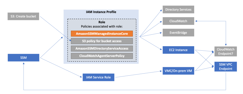
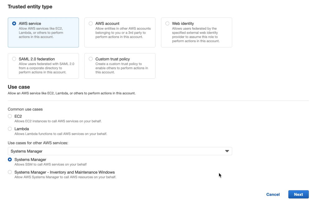
Navigate to IAM in the AWS Console and create a new role. Select “Trusted entity type” to be “AWS Service” and the “Use Case” to be “Systems Manager”.
Under Permissions, search for and select the following:

  • CloudWatchAgentServerPolicy
  • AmazonSSMDirectoryServiceAccess
  • AmazonSSMManagedInstanceCore
  • The policy previously created for the SSM S3 bucket

5. Creating the systems manager VPC endpoints

Endpoints for AWS SSM can be created in the VMware Cloud on AWS Connected VPC. This is to provide the VMs in VMware Cloud on AWS a path to communicate with AWS SSM via the connected VPC ENI rather than accessing AWS SSM over the internet. This is both secure and as long as the SSM endpoint in the connected VPC is in the same availability zone as the VMware Cloud on AWS SDDC, communication is free of charge.

Create endpoints for the SSM service and, optionally, also KMS, Logs and SSM messages services as per the below:

6. Creating the R53 DNS inbound endpoint

Creating the SSM endpoint is the first step but the VMs in VMware Cloud on AWS must also be directed to that endpoint rather than the public SSM IP addresses. Rather than modifying each VM, a more efficient way is to add a Route 53 inbound endpoint to the Connected VPC. If the CGW DHCP server for the VMware Cloud on AWS VM segments is then updated to point DNS to that Route 53 endpoint, the VMs will automatically resolve the SSM FQDN to the endpoint private IP address.
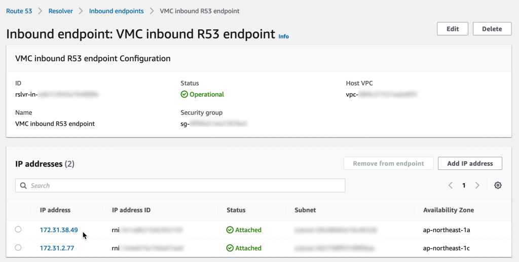
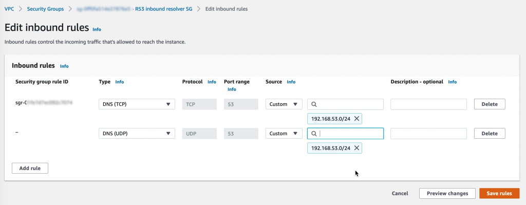
Make sure that the security group for the inbound R53 endpoints allow DNS on both TCP and UDP from the VMware Cloud on AWS CGW network segments.
7. Pointing CGW DNS to R53

In the VMware Cloud on AWS console, navigate to “Networking & Security” and select “Segments” under Network. Update the network segments for the VMs to use the R53 inbound endpoint IP addresses.
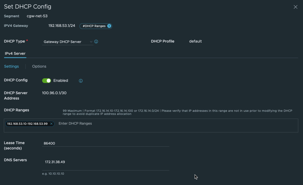
The VMs connected to the CGW network segment may need to be disconnected and then re-connected to the network in vCenter or restart the networking from the OS side for the changes to take effect.

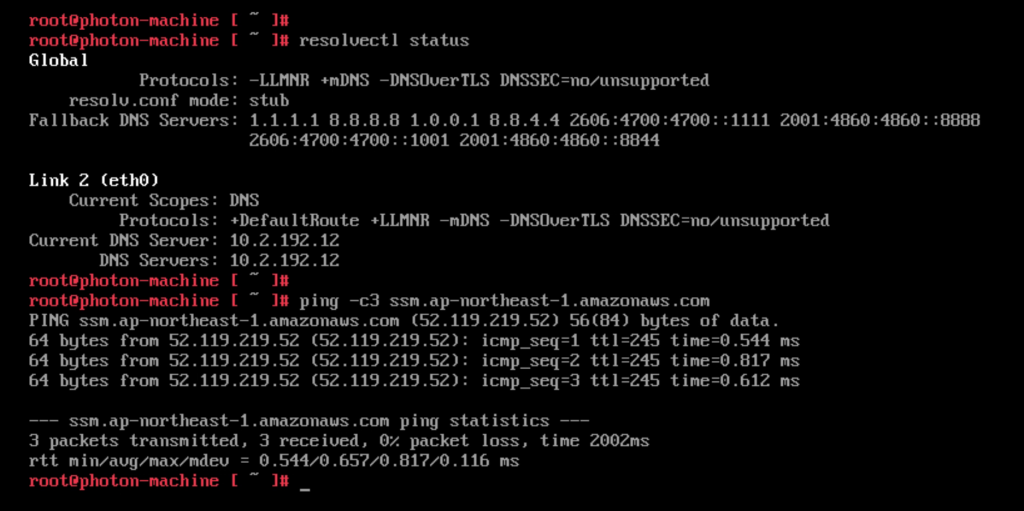
Before changing the DNS to point to the R53 inbound endpoint the VM in VMware Cloud on AWS resolves the regional SSM endpoint to the public IP address. Communication is done via the IGW in the VMware Cloud on AWS environment.
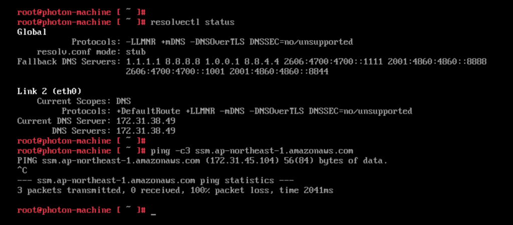
After updating the DNS the VM resolves the SSM endpoint to the private endpoint created earlier. Communication is over the Connected VPC ENI. Note: The ping doesn’t succeed since the security group for SSM blocks ICMP. However, the command shows that the VM correctly resolves the regional SSM endpoint to the private IP address in the Connected VPC.
8. Creating the SDDC firewall rules

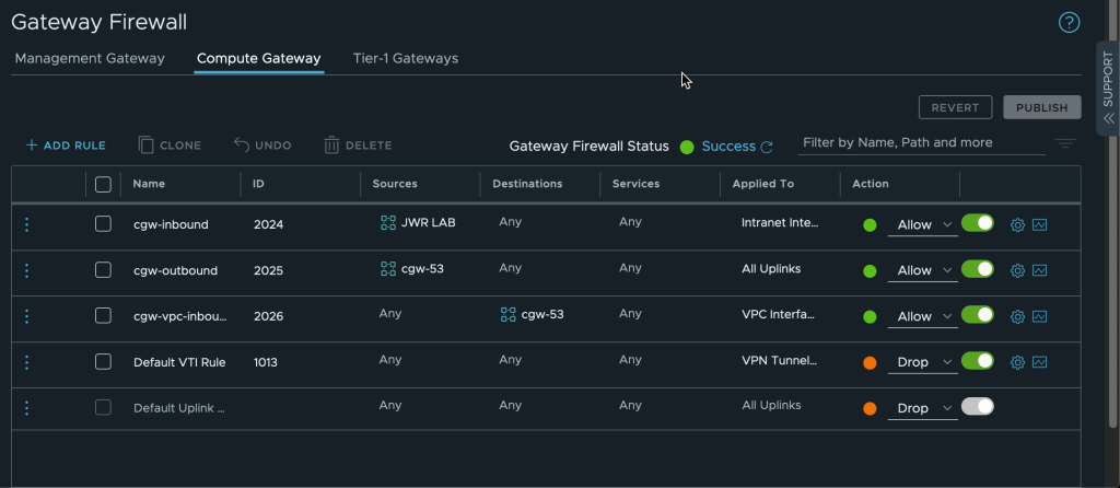
The network segments connected to the VMware Cloud on AWS CGW router need access to both SSM and R53 services in the Connected VPC. AWS SSM also need to be able to access the VMware Cloud on AWS VMs over the Connected VPC ENI. Create firewall rules on the CGW to allow this traffic. In the screenshot below the VMware Cloud on AWS VM network “cgw-53” is allowed to communicate anywhere over any uplink while inbound traffic to the same network is allowed over the VPC interface only.
9. Creating a hybrid activation

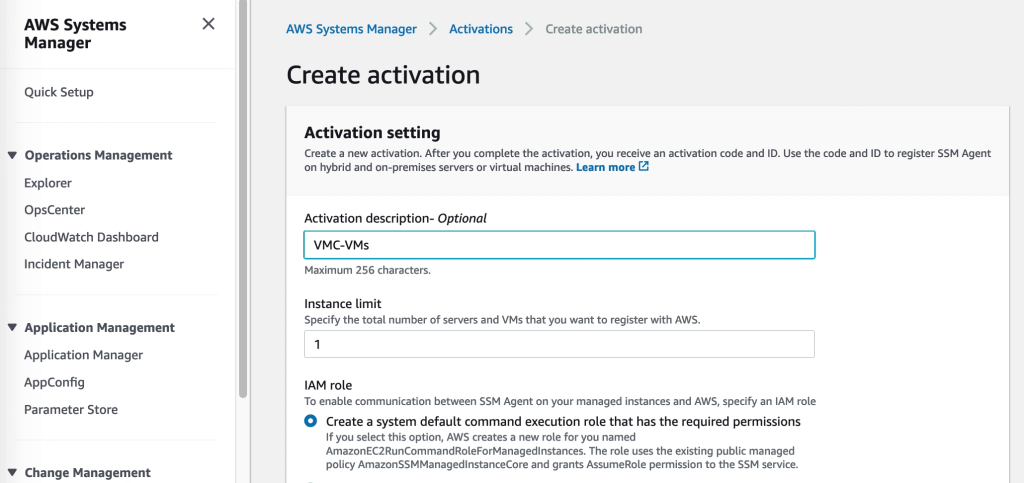
Virtual machines external to EC2 are added to AWS SSM through a “Hybrid activation”. This is created via the SSM section of the AWS Console and generates an ID and a code for a preset number of VMs. These can be used as credentials in the next step where the SSM agent is installed and the VMs are registered with SSM
10. VM configuration: Installing the SSM agent and registering with SSM

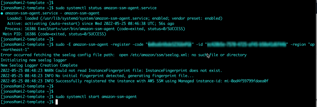
Instances on EC2 normally come with the SSM agent pre-installed. For VMs in VMware Cloud on AWS or on-premises VMware environments the agent needs to be installed. This is both quick and easy to do. The details for agent installation for a multitude of OS types are described in the SSM user guide. In this example the agent will be installed on a Linux VM. Instructions for Windows VMs can be found here.

After downloading and installing the agent, the Hybrid Activation code and ID from step 9 above are used to register the VM with AWS SSM
Verifying that the VM is available in Systems Manager. Note that in contrast from EC2 instances, the VMware Cloud on AWS VM is prefixed with an “mi-” rather than just an “i-”. This is an indication it is a Managed Instance external to EC2. Of course labels and groups can also be used to keep the managed nodes apart, but the Node ID is a quick indicator of where it comes from.

Managing the VMs in Systems Manager

Viewing the VM inventory

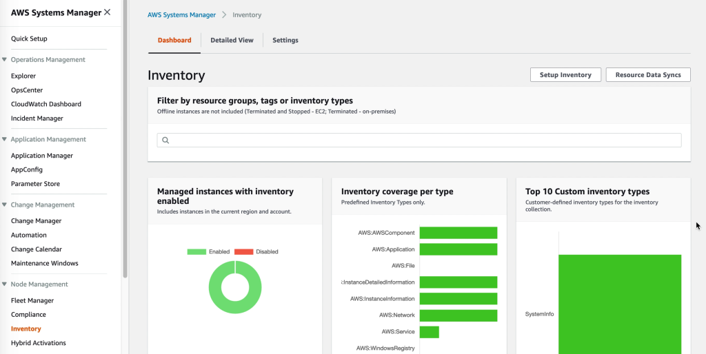
Once the AWS SSM agent is installed it will start collecting the software inventory of the VM. This data is available through the SSM Inventory console but can also be exported to S3 for further processing by Athena. Detailed reports can be created by pointing QuickSight to the Athena data.
Accessing VM registry, logs and filesystem

The VM filesystem, performance metrics, system logs and even registry for Windows VMs is accessible directly through the AWS Console for each VM registered with SSM. Administering the VMs though the AWS Console reduces the need for direct desktop or shell access. For some features, like performance metrics, please be sure to enable KMS encryption in the SSM general settings.

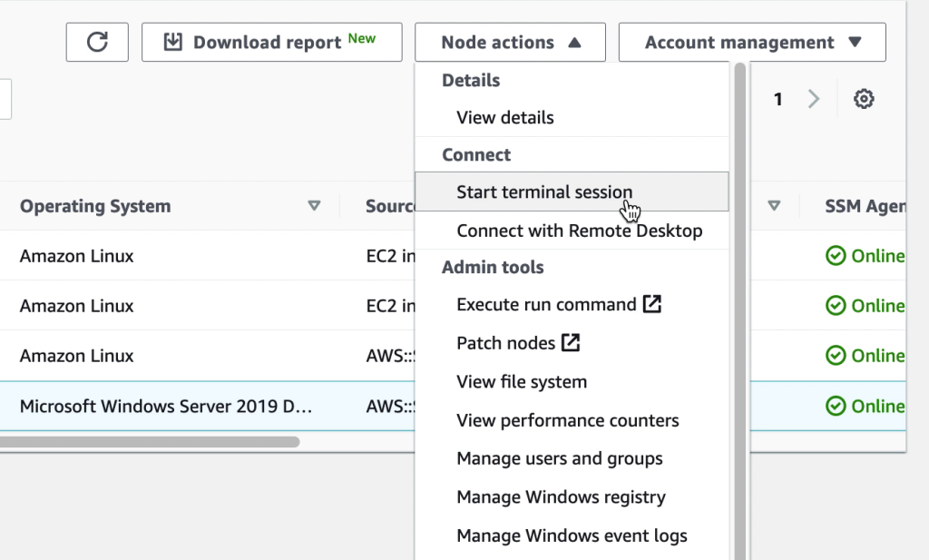
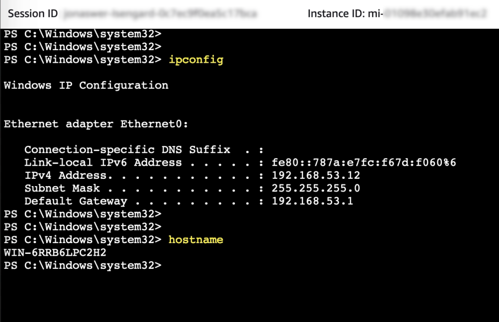
Accessing the VM PowerShell console

While PowerShell or a shell prompt on a VM can be accessed over RDP or SSH, having the ability to quickly connect to a VM console through SSM helps streamline system administration.
Accessing the VM desktop

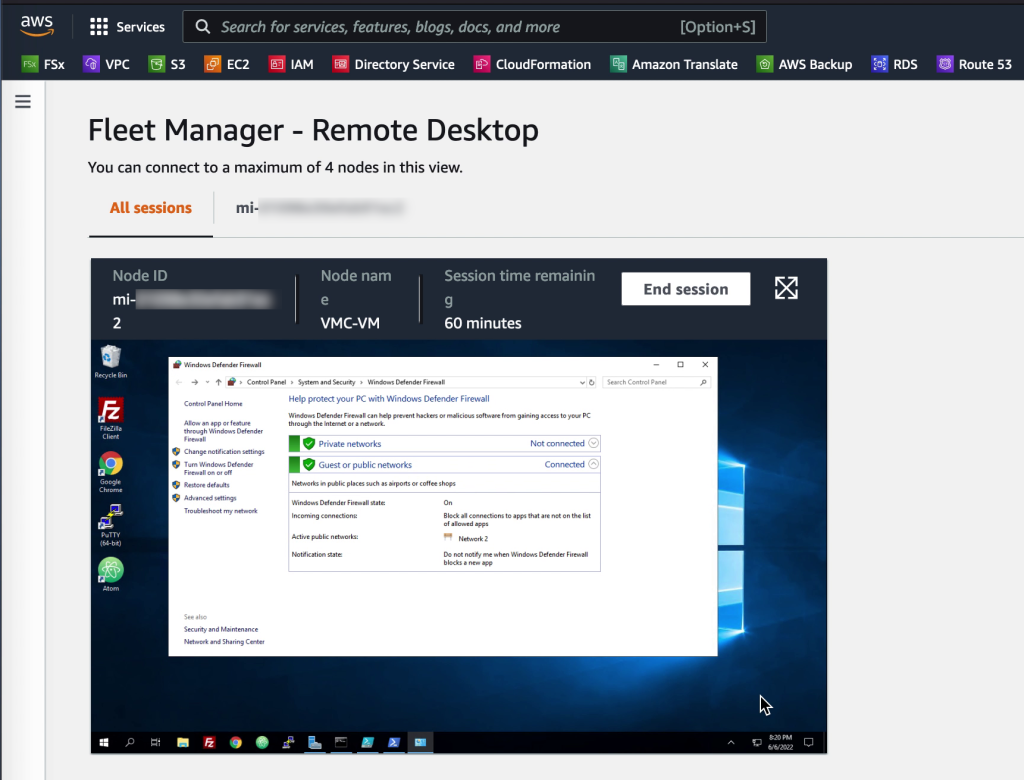
For Windows VMs it is possible to quickly open an RDP session even though the firewall on the VM is enabled and blocking RDP. The SSM agent creates a loopback connection which enables access from the AWS console. Up to four sessions can be opened in a single SSM Session Manager window. The session window can be maximized to view the VM in full screen
Patching VMs

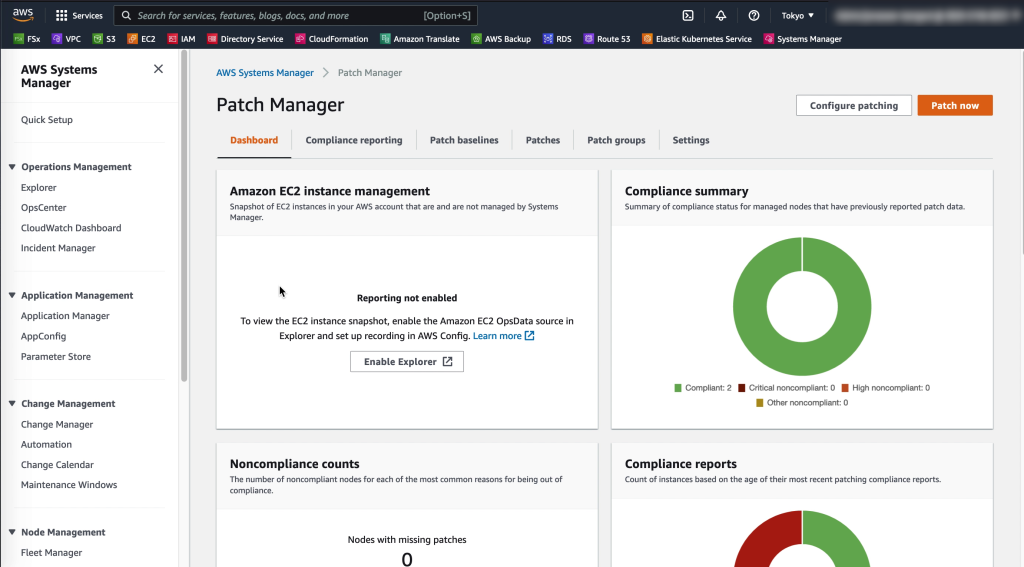
Through SSM Patch manager, patch baselines and maintenance windows can easily be created and applied to the managed VMware VMs as well as EC2 instances to ensure they are up to date and have the highest level of protection possible
Conclusion

VMware Cloud on AWS is not a standalone solution but integrates well with a variety of AWS native services. In this blog post AWS Systems Manager and related services were leveraged to enhance security of VMs running on VMware Cloud on AWS by centralizing access controls and automating OS patch management.

Further reading

Capture VMware performance data using Live Optics

Gaining insights into the details of what makes up a large and complex VMware environment can be challenging. This is especially true if gathering individual VM performance data is part of the goal.

Live Optics, a tool created by Dell Technologies, is a great way to gather performance data from a vSphere environment over time. It can run on a laptop or VM and has the ability to either take a snapshot of the environment without performance data or to run over a period from 10min to 7 days and report also on performance.

The data can be streamed continuously to a Live Optics endpoint. In this case the data gathering process can be viewed live through the Live Optics web portal. Alternatively the data can be saved locally as an encrypted SIOKIT file during the capture process and then be uploaded to the Live Optics portal once data collection is complete.

Below is a 5 min video showing the entire process of account creation, collection download and report export in Excel format for reference

New blog post for migrating from on-premises VMware vSphere to VMware Cloud on AWS using FSx for NetApp ONTAP SnapMirror

Recently published blog post showing the pros and cons for migrating virtual machines using SnapMirror and also some ideas about how to use a similar methodology for disaster recovery purposes

Access the blog on the AWS official web page here:

https://aws.amazon.com/blogs/apn/vmware-cloud-on-aws-disaster-recovery-with-amazon-fsx-for-netapp-ontap-and-snapmirror/

Migrating VMs from on-premises vSphere to VMware Cloud on AWS using NetApp SnapMirror

Note: This blog post is part of the 2022 edition of the vExpert Japan Advent Calendar series for the 9th of December.

Migration from an on-premises environment to VMware Cloud on AWS can be done in a variety of ways. The most commonly used (and also recommended) method is Hybrid Cloud Extensions – HCX. However, if VMs are stored on a NetApp ONTAP appliance in the on-prem environment, the volume the VMs reside on can easily be copied to the cloud using SnapMirror. Once copied, the volume can be mounted to VMware Cloud on AWS and the VMs imported. This may be a useful method of migration provided some downtime is acceptable.

Tip: If you are just testing things out, NetApp offers a downloadable virtual ONTAP appliance which can be deployed with all features enabled for 60 days.

Prerequisites

  • Since SnapMirror is a licensed feature, please make sure a license is available on the on-prem environment. FSx for NetApp ONTAP includes SnapMirror functionality
  • SnapMirror only works between a limited range of ONTAP versions. Verify that the on-prem array is compatible with FSxN. The version of FSxN at the time of writing is “NetApp Release 9.11.1P3”. Verify your version (“version” command from CLI) and compare with the list for “SnapMirror DR relationships” provided by NetApp here: https://docs.netapp.com/us-en/ontap/data-protection/compatible-ontap-versions-snapmirror-concept.html#snapmirror-synchronous-relationships
  • Ensure the FSxN ENIs have a security group assigned allowing ICMP and TCP (in and outbound) on ports 11104 and 11105

Outline of steps

  1. Create an FSx for NetApp ONTAP (FSxN) file system
  2. Create a target volume in FSxN
  3. Set up cluster peering between on-prem ONTAP and FSxN
  4. Set up Storage VM (SVM) peering between on-prem ONTAP and FSxN
  5. Configure SnapMirror and Initialize the data sync
  6. Break the mirror (we’ll show deal with the 7 years of bad luck in a future blog post)
  7. Add an NFS mount point for the FSxN volume
  8. Mount the volume on VMware Cloud on AWS
  9. Import the VMs into vCenter
  10. Configure network for the VMs

Architecture diagram

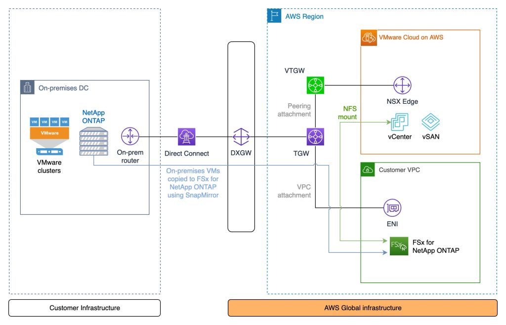
The peering relationship between NetApp ONTAP on-prem and in FSxN requires private connectivity. The diagram shows Direct Connect, but a VPN terminating at the TGW can also be used

Video of the process

This video shows all the steps outlined previously with the exception of creating the FSxN file system – although that is a very simple process and hardly worth covering in detail regardless

Commands

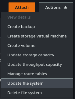
Open SSH sessions to both the on-premises ONTAP array and FSxN. The FSxN username will be “fsxadmin”. If not known, the password can be (re)set through the “Actions” menu under “Update file system” after selecting the FSxN file system in the AWS Console.

Step 1: [FSxN] Create the file system in AWS

The steps for this are straight-forward and already covered in detail here: https://docs.aws.amazon.com/fsx/latest/ONTAPGuide/getting-started-step1.html

Step 2: [FSxN] Create the target volume

Note that the volume is listed as “DP” for Data Protection. This is required for SnapMirror.

FsxId0e4a2ca9c02326f50::> vol create -vserver svm-fsxn-multi-az-2 -volume snapmirrorDest -aggregate aggr1 -size 200g -type DP -tiering-policy all
[Job 1097] Job succeeded: Successful

FsxId0e4a2ca9c02326f50::>
FsxId0e4a2ca9c02326f50::> vol show
Vserver   Volume       Aggregate    State      Type       Size  Available Used%
--------- ------------ ------------ ---------- ---- ---------- ---------- -----

svm-fsxn-multi-az-2
          onprem_vm_volume_clone
                       aggr1        online     RW         40GB    36.64GB    3%
svm-fsxn-multi-az-2
          snapmirrorDest
                       aggr1        online     DP        200GB    200.0GB    0%
svm-fsxn-multi-az-2
          svm_fsxn_multi_az_2_root
                       aggr1        online     RW          1GB    972.1MB    0%
8 entries were displayed.

FsxId0e4a2ca9c02326f50::>

Step 3a: [On-prem] Create the cluster peering relationship

Get the intercluster IP addresses from the on-prem environment

JWR-ONTAP::> network interface show -role intercluster
            Logical    Status     Network            Current       Current Is
Vserver     Interface  Admin/Oper Address/Mask       Node          Port    Home
----------- ---------- ---------- ------------------ ------------- ------- ----
JWR-ONTAP
            Intercluster-IF-1
                         up/up    10.70.1.121/24     JWR-ONTAP-01  e0a     true
            Intercluster-IF-2
                         up/up    10.70.1.122/24     JWR-ONTAP-01  e0b     true
2 entries were displayed.

Step 3b: [FSxN] Create the cluster peering relationship

FsxId0e4a2ca9c02326f50::> cluster peer create -address-family ipv4 -peer-addrs 10.70.1.121, 10.70.1.122

Notice: Use a generated passphrase or choose a passphrase of 8 or more characters. To ensure the authenticity of the peering relationship, use a phrase or sequence of characters that would be hard to guess.

Enter the passphrase:
Confirm the passphrase:

Notice: Now use the same passphrase in the "cluster peer create" command in the other cluster.

FsxId0e4a2ca9c02326f50::> cluster peer show
Peer Cluster Name         Cluster Serial Number Availability   Authentication
------------------------- --------------------- -------------- --------------
JWR-ONTAP                 1-80-000011           Available      ok

Step 3c: [FSxN] Create the cluster peering relationship

Get the intercluster IP addresses from the FSxN environment

FsxId0e4a2ca9c02326f50::> network interface show -role intercluster
            Logical    Status     Network            Current       Current Is
Vserver     Interface  Admin/Oper Address/Mask       Node          Port    Home
----------- ---------- ---------- ------------------ ------------- ------- ----
FsxId0e4a2ca9c02326f50
            inter_1      up/up    172.16.0.163/24    FsxId0e4a2ca9c02326f50-01
                                                                   e0e     true
            inter_2      up/up    172.16.1.169/24    FsxId0e4a2ca9c02326f50-02
                                                                   e0e     true
2 entries were displayed.

Step 3d: [On-prem] Create the cluster peering relationship

Use the same passphrase as when using the cluster peer create command on the FSxN side in Step 3b

JWR-ONTAP::> cluster peer create -address-family ipv4 -peer-addrs 172.16.0.163, 172.16.0.163

Step 4a: [FSxN] Create the Storage VM (SVM) peering relationship

FsxId0e4a2ca9c02326f50::> vserver peer create -vserver svm-fsxn-multi-az-2 -peer-vserver svm0 -peer-cluster JWR-ONTAP -applications snapmirror -local-name onprem

Info: [Job 145] 'vserver peer create' job queued

Step 4b: [On-prem] Create the Storage VM (SVM) peering relationship

After the peer accept command completes, verify the relationship using “vserver peer show-all”.

JWR-ONTAP::> vserver peer accept -vserver svm0 -peer-vserver svm-fsxn-multi-az-2 -local-name fsxn-peer

Step 5a: [FSxN] Create the SnapMirror relationship

FsxId0e4a2ca9c02326f50::> snapmirror create -source-path onprem:vmware -destination-path svm-fsxn-multi-az-2:snapmirrorDest -vserver svm-fsxn-multi-az-2 -throttle unlimited
Operation succeeded: snapmirror create for the relationship with destination "svm-fsxn-multi-az-2:snapmirrorDest".

FsxId0e4a2ca9c02326f50::> snapmirror show
                                                                       Progress
Source            Destination Mirror  Relationship   Total             Last
Path        Type  Path        State   Status         Progress  Healthy Updated
----------- ---- ------------ ------- -------------- --------- ------- --------
onprem:vmware
XDP  svm-fsxn-multi-az-2:snapmirrorDest
Uninitialized
Idle           -         true    -

Step 5b: [FSxN] Initialize the SnapMirror relationship

This will start the data copy from on-prem to AWS

FsxId0e4a2ca9c02326f50::> snapmirror initialize -destination-path svm-fsxn-multi-az-2:snapmirrorDest -source-path onprem:vmware
Operation is queued: snapmirror initialize of destination "svm-fsxn-multi-az-2:snapmirrorDest".

FsxId0e4a2ca9c02326f50::> snapmirror show
                                                                     Progress
Source            Destination Mirror  Relationship   Total             Last
Path        Type  Path        State   Status         Progress  Healthy Updated
----------- ---- ------------ ------- -------------- --------- ------- --------
onprem:vmware
          XDP  svm-fsxn-multi-az-2:snapmirrorDest
                            Uninitialized
                                    Transferring   0B        true    09/20 08:55:05

FsxId0e4a2ca9c02326f50::> snapmirror show
                                                                     Progress
Source            Destination Mirror  Relationship   Total             Last
Path        Type  Path        State   Status         Progress  Healthy Updated
----------- ---- ------------ ------- -------------- --------- ------- --------
onprem:vmware
          XDP  svm-fsxn-multi-az-2:snapmirrorDest
                            Snapmirrored
                                    Finalizing     0B        true    09/20 08:58:46

FsxId0e4a2ca9c02326f50::> snapmirror show
                                                                     Progress
Source            Destination Mirror  Relationship   Total             Last
Path        Type  Path        State   Status         Progress  Healthy Updated
----------- ---- ------------ ------- -------------- --------- ------- --------
onprem:vmware
          XDP  svm-fsxn-multi-az-2:snapmirrorDest
                            Snapmirrored
                                    Idle           -         true    -

FsxId0e4a2ca9c02326f50::>

Step 6: [FSxN] Break the mirror

FsxId0e4a2ca9c02326f50::> snapmirror break -destination-path svm-fsxn-multi-az-2:snapmirrorDest
Operation succeeded: snapmirror break for destination "svm-fsxn-multi-az-2:snapmirrorDest".

Step 7: [FSxN] Add an NFS mount point for the FSxN volume

FsxId0e4a2ca9c02326f50::> volume mount -volume snapmirrorDest -junction-path /fsxn-snapmirror-volume

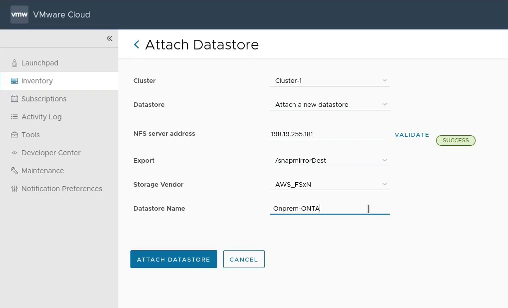
Step 8: [VMC] Mount the FSxN volume in VMware Cloud on AWS

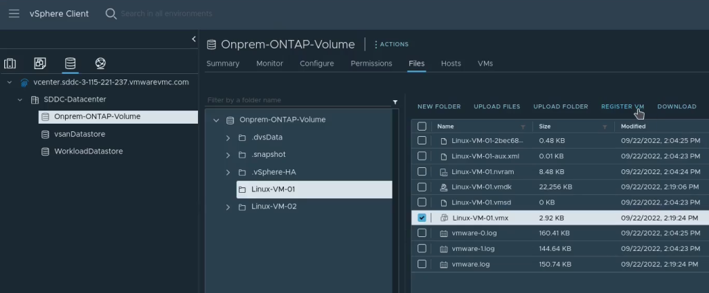
Step 9: [VMC] Import the VMs into vCenter in VMware Cloud on AWS

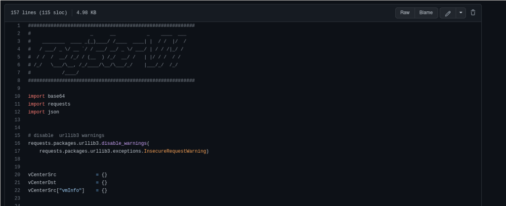
This can be done manually as per the screenshot below, or automated with a script

Manual import of VMs from the FSxN volume into VMware Cloud on AWS

Importing using a Python script (initial release – may have rough edges): https://github.com/jonas-werner/vmware-vm-import-from-datastore/blob/main/registerVm.py

Video on how to use the script can be found here:

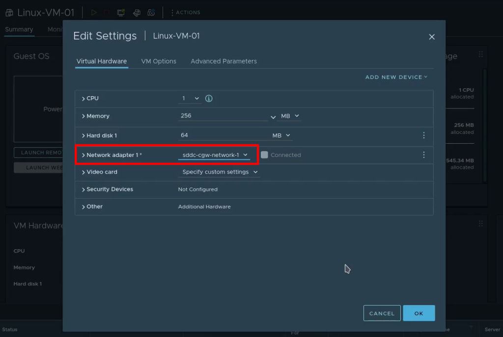
Step 10: [VMC] Configure the VM network prior to powering on

Wrap-up

That’s all there is to migrating VMs using SnapMirror between on-prem VMware and VMware Cloud on AWS environments. Hopefully this has been useful. Thank you for reading!