
Note: This blog post is part of the 2022 edition of the vExpert Japan Advent Calendar series for the 9th of December.
Migration from an on-premises environment to VMware Cloud on AWS can be done in a variety of ways. The most commonly used (and also recommended) method is Hybrid Cloud Extensions – HCX. However, if VMs are stored on a NetApp ONTAP appliance in the on-prem environment, the volume the VMs reside on can easily be copied to the cloud using SnapMirror. Once copied, the volume can be mounted to VMware Cloud on AWS and the VMs imported. This may be a useful method of migration provided some downtime is acceptable.
Tip: If you are just testing things out, NetApp offers a downloadable virtual ONTAP appliance which can be deployed with all features enabled for 60 days.
Prerequisites
- Since SnapMirror is a licensed feature, please make sure a license is available on the on-prem environment. FSx for NetApp ONTAP includes SnapMirror functionality
- SnapMirror only works between a limited range of ONTAP versions. Verify that the on-prem array is compatible with FSxN. The version of FSxN at the time of writing is “NetApp Release 9.11.1P3”. Verify your version (“version” command from CLI) and compare with the list for “SnapMirror DR relationships” provided by NetApp here: https://docs.netapp.com/us-en/ontap/data-protection/compatible-ontap-versions-snapmirror-concept.html#snapmirror-synchronous-relationships
- Ensure the FSxN ENIs have a security group assigned allowing ICMP and TCP (in and outbound) on ports 11104 and 11105
Outline of steps
- Create an FSx for NetApp ONTAP (FSxN) file system
- Create a target volume in FSxN
- Set up cluster peering between on-prem ONTAP and FSxN
- Set up Storage VM (SVM) peering between on-prem ONTAP and FSxN
- Configure SnapMirror and Initialize the data sync
- Break the mirror (we’ll show deal with the 7 years of bad luck in a future blog post)
- Add an NFS mount point for the FSxN volume
- Mount the volume on VMware Cloud on AWS
- Import the VMs into vCenter
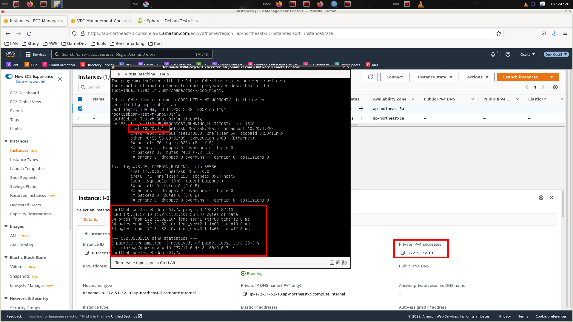
- Configure network for the VMs
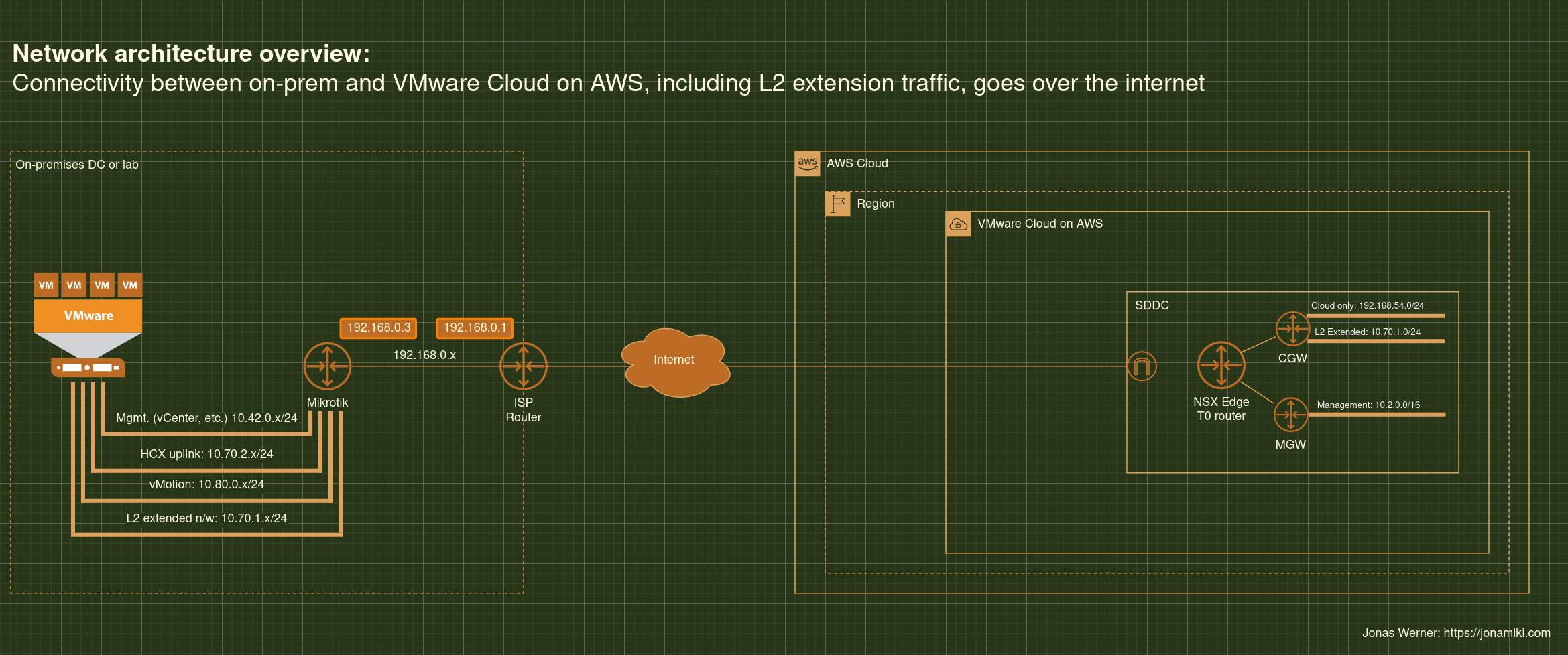
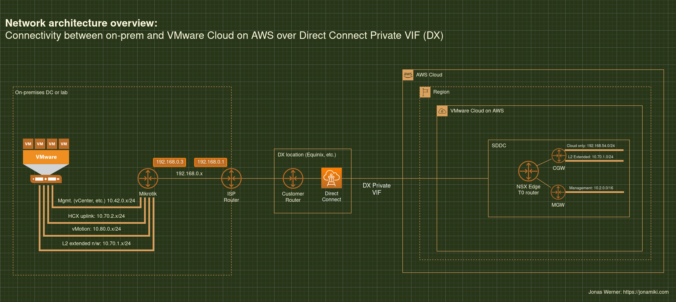
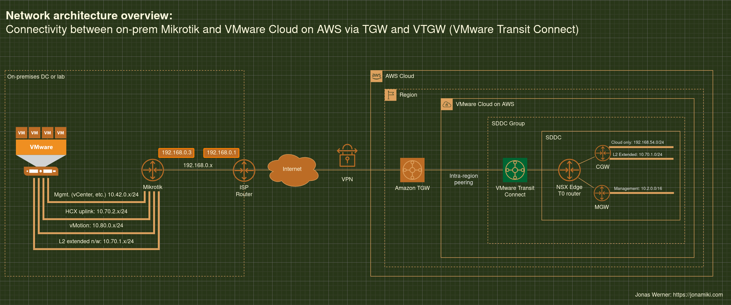
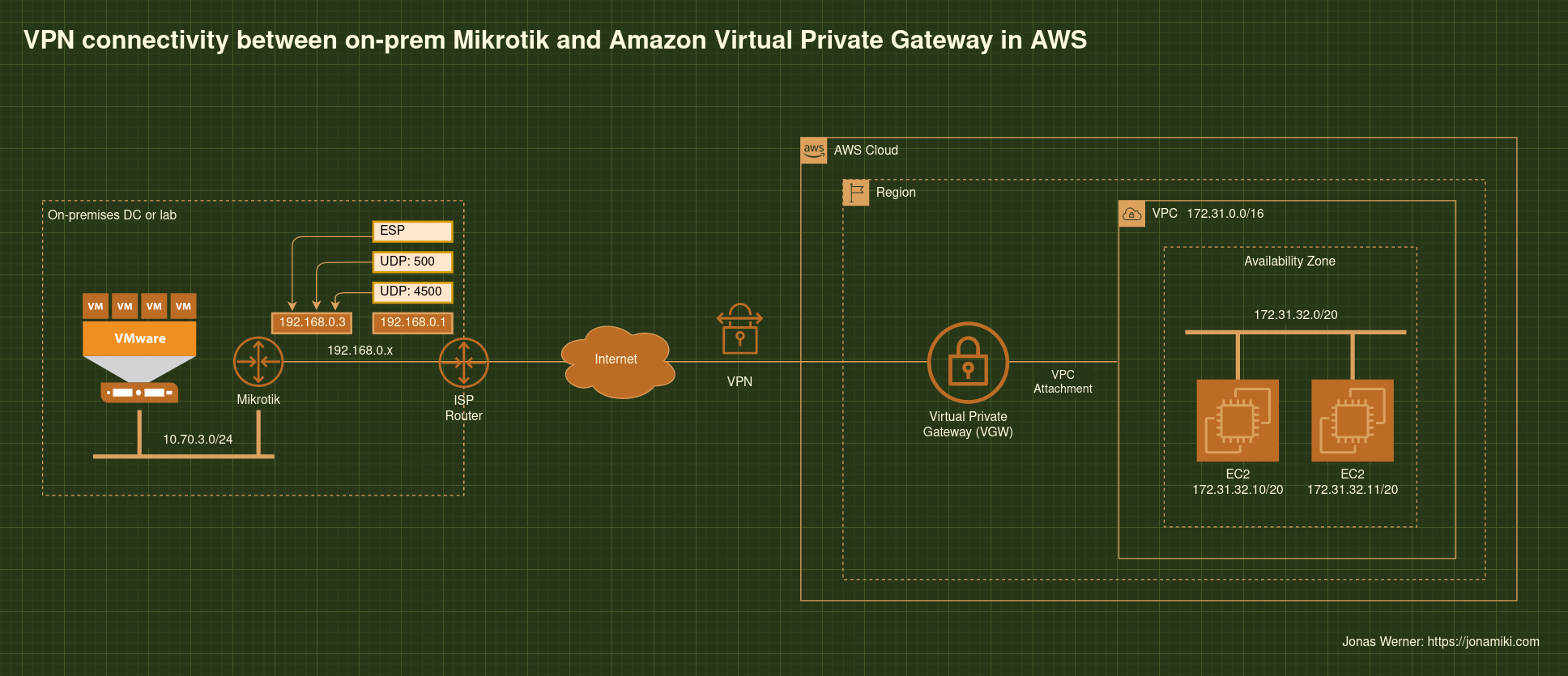
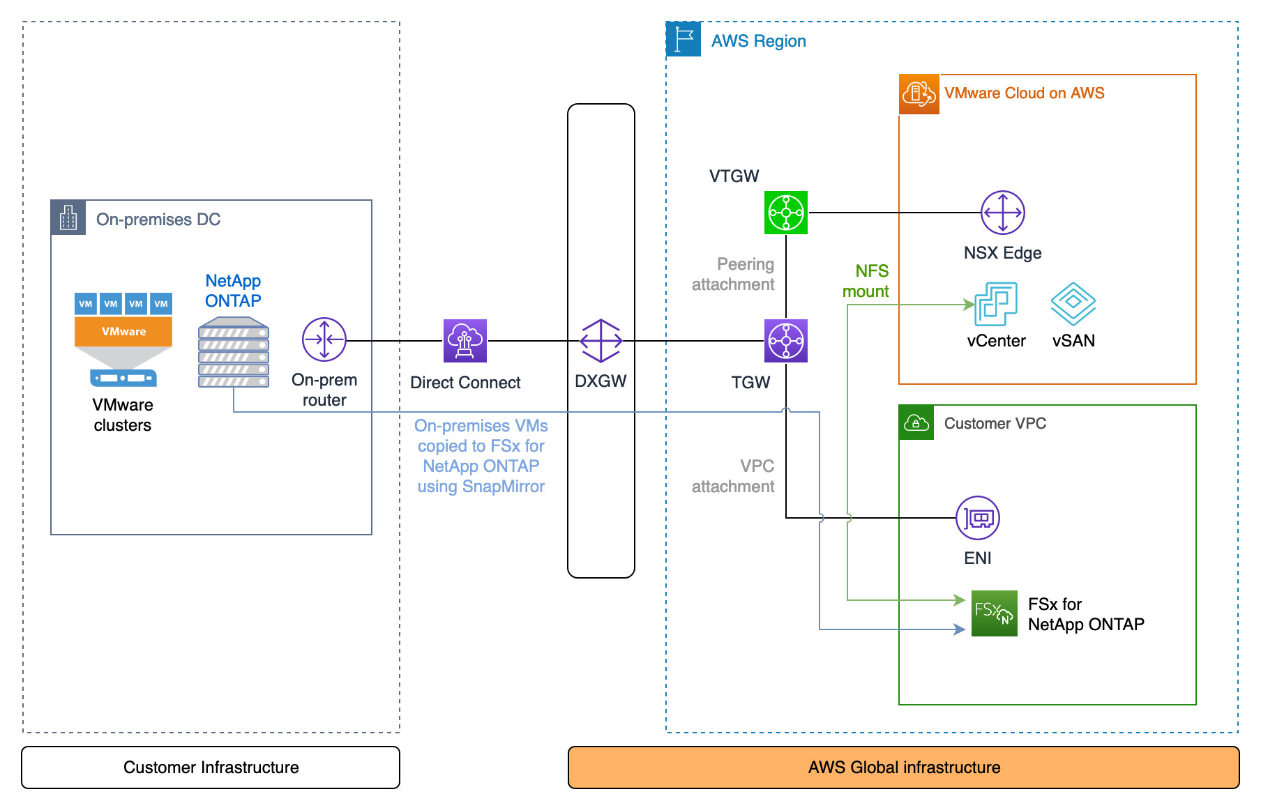
Architecture diagram
The peering relationship between NetApp ONTAP on-prem and in FSxN requires private connectivity. The diagram shows Direct Connect, but a VPN terminating at the TGW can also be used
Video of the process
This video shows all the steps outlined previously with the exception of creating the FSxN file system – although that is a very simple process and hardly worth covering in detail regardless
Commands
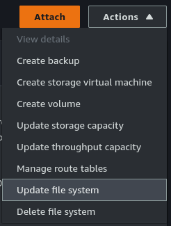
Open SSH sessions to both the on-premises ONTAP array and FSxN. The FSxN username will be “fsxadmin”. If not known, the password can be (re)set through the “Actions” menu under “Update file system” after selecting the FSxN file system in the AWS Console.
Step 1: [FSxN] Create the file system in AWS
The steps for this are straight-forward and already covered in detail here: https://docs.aws.amazon.com/fsx/latest/ONTAPGuide/getting-started-step1.html
Step 2: [FSxN] Create the target volume
Note that the volume is listed as “DP” for Data Protection. This is required for SnapMirror.
FsxId0e4a2ca9c02326f50::> vol create -vserver svm-fsxn-multi-az-2 -volume snapmirrorDest -aggregate aggr1 -size 200g -type DP -tiering-policy all
[Job 1097] Job succeeded: Successful

FsxId0e4a2ca9c02326f50::>
FsxId0e4a2ca9c02326f50::>
FsxId0e4a2ca9c02326f50::> vol show
Vserver   Volume       Aggregate    State      Type       Size  Available Used%
--------- ------------ ------------ ---------- ---- ---------- ---------- -----

svm-fsxn-multi-az-2
          onprem_vm_volume_clone
                       aggr1        online     RW         40GB    36.64GB    3%
svm-fsxn-multi-az-2
          snapmirrorDest
                       aggr1        online     DP        200GB    200.0GB    0%
svm-fsxn-multi-az-2
          svm_fsxn_multi_az_2_root
                       aggr1        online     RW          1GB    972.1MB    0%
8 entries were displayed.

FsxId0e4a2ca9c02326f50::>
FsxId0e4a2ca9c02326f50::>
Step 3a: [On-prem] Create the cluster peering relationship
Get the intercluster IP addresses from the on-prem environment
JWR-ONTAP::> network interface show -role intercluster
            Logical    Status     Network            Current       Current Is
Vserver     Interface  Admin/Oper Address/Mask       Node          Port    Home
----------- ---------- ---------- ------------------ ------------- ------- ----
JWR-ONTAP
            Intercluster-IF-1
                         up/up    10.70.1.121/24     JWR-ONTAP-01  e0a     true
            Intercluster-IF-2
                         up/up    10.70.1.122/24     JWR-ONTAP-01  e0b     true
2 entries were displayed.
Step 3b: [FSxN] Create the cluster peering relationship
FsxId0e4a2ca9c02326f50::> cluster peer create -address-family ipv4 -peer-addrs 10.70.1.121, 10.70.1.122

Notice: Use a generated passphrase or choose a passphrase of 8 or more characters. To ensure the authenticity of the peering relationship, use a phrase or sequence of characters that would be hard to guess.

Enter the passphrase:
Confirm the passphrase:

Notice: Now use the same passphrase in the "cluster peer create" command in the other cluster.

FsxId0e4a2ca9c02326f50::> cluster peer show
Peer Cluster Name         Cluster Serial Number Availability   Authentication
------------------------- --------------------- -------------- --------------
JWR-ONTAP                 1-80-000011           Available      ok
Step 3c: [FSxN] Create the cluster peering relationship
Get the intercluster IP addresses from the FSxN environment
FsxId0e4a2ca9c02326f50::> network interface show -role intercluster
            Logical    Status     Network            Current       Current Is
Vserver     Interface  Admin/Oper Address/Mask       Node          Port    Home
----------- ---------- ---------- ------------------ ------------- ------- ----
FsxId0e4a2ca9c02326f50
            inter_1      up/up    172.16.0.163/24    FsxId0e4a2ca9c02326f50-01
                                                                   e0e     true
            inter_2      up/up    172.16.1.169/24    FsxId0e4a2ca9c02326f50-02
                                                                   e0e     true
2 entries were displayed.
Step 3d: [On-prem] Create the cluster peering relationship
Use the same passphrase as when using the cluster peer create command on the FSxN side in Step 3b
JWR-ONTAP::> cluster peer create -address-family ipv4 -peer-addrs 172.16.0.163, 172.16.0.163Step 4a: [FSxN] Create the Storage VM (SVM) peering relationship
FsxId0e4a2ca9c02326f50::> vserver peer create -vserver svm-fsxn-multi-az-2 -peer-vserver svm0 -peer-cluster JWR-ONTAP -applications snapmirror -local-name onprem

Info: [Job 145] 'vserver peer create' job queued
Step 4b: [On-prem] Create the Storage VM (SVM) peering relationship
After the peer accept command completes, verify the relationship using “vserver peer show-all”.
JWR-ONTAP::> vserver peer accept -vserver svm0 -peer-vserver svm-fsxn-multi-az-2 -local-name fsxn-peerStep 5a: [FSxN] Create the SnapMirror relationship
FsxId0e4a2ca9c02326f50::> snapmirror create -source-path onprem:vmware -destination-path svm-fsxn-multi-az-2:snapmirrorDest -vserver svm-fsxn-multi-az-2 -throttle unlimited
Operation succeeded: snapmirror create for the relationship with destination "svm-fsxn-multi-az-2:snapmirrorDest".

FsxId0e4a2ca9c02326f50::> snapmirror show
                                                                       Progress
Source            Destination Mirror  Relationship   Total             Last
Path        Type  Path        State   Status         Progress  Healthy Updated
----------- ---- ------------ ------- -------------- --------- ------- --------
onprem:vmware
XDP  svm-fsxn-multi-az-2:snapmirrorDest
Uninitialized
Idle           -         true    -
Step 5b: [FSxN] Initialize the SnapMirror relationship
This will start the data copy from on-prem to AWS
FsxId0e4a2ca9c02326f50::> snapmirror initialize -destination-path svm-fsxn-multi-az-2:snapmirrorDest -source-path onprem:vmware
Operation is queued: snapmirror initialize of destination "svm-fsxn-multi-az-2:snapmirrorDest".

FsxId0e4a2ca9c02326f50::> snapmirror show
                                                                     Progress
Source            Destination Mirror  Relationship   Total             Last
Path        Type  Path        State   Status         Progress  Healthy Updated
----------- ---- ------------ ------- -------------- --------- ------- --------
onprem:vmware
          XDP  svm-fsxn-multi-az-2:snapmirrorDest
                            Uninitialized
                                    Transferring   0B        true    09/20 08:55:05

FsxId0e4a2ca9c02326f50::> snapmirror show
                                                                     Progress
Source            Destination Mirror  Relationship   Total             Last
Path        Type  Path        State   Status         Progress  Healthy Updated
----------- ---- ------------ ------- -------------- --------- ------- --------
onprem:vmware
          XDP  svm-fsxn-multi-az-2:snapmirrorDest
                            Snapmirrored
                                    Finalizing     0B        true    09/20 08:58:46

FsxId0e4a2ca9c02326f50::> snapmirror show
                                                                     Progress
Source            Destination Mirror  Relationship   Total             Last
Path        Type  Path        State   Status         Progress  Healthy Updated
----------- ---- ------------ ------- -------------- --------- ------- --------
onprem:vmware
          XDP  svm-fsxn-multi-az-2:snapmirrorDest
                            Snapmirrored
                                    Idle           -         true    -

FsxId0e4a2ca9c02326f50::>
Step 6: [FSxN] Break the mirror
FsxId0e4a2ca9c02326f50::> snapmirror break -destination-path svm-fsxn-multi-az-2:snapmirrorDest
Operation succeeded: snapmirror break for destination "svm-fsxn-multi-az-2:snapmirrorDest".
Step 7: [FSxN] Add an NFS mount point for the FSxN volume
FsxId0e4a2ca9c02326f50::> volume mount -volume snapmirrorDest -junction-path /fsxn-snapmirror-volumeStep 8: [VMC] Mount the FSxN volume in VMware Cloud on AWS
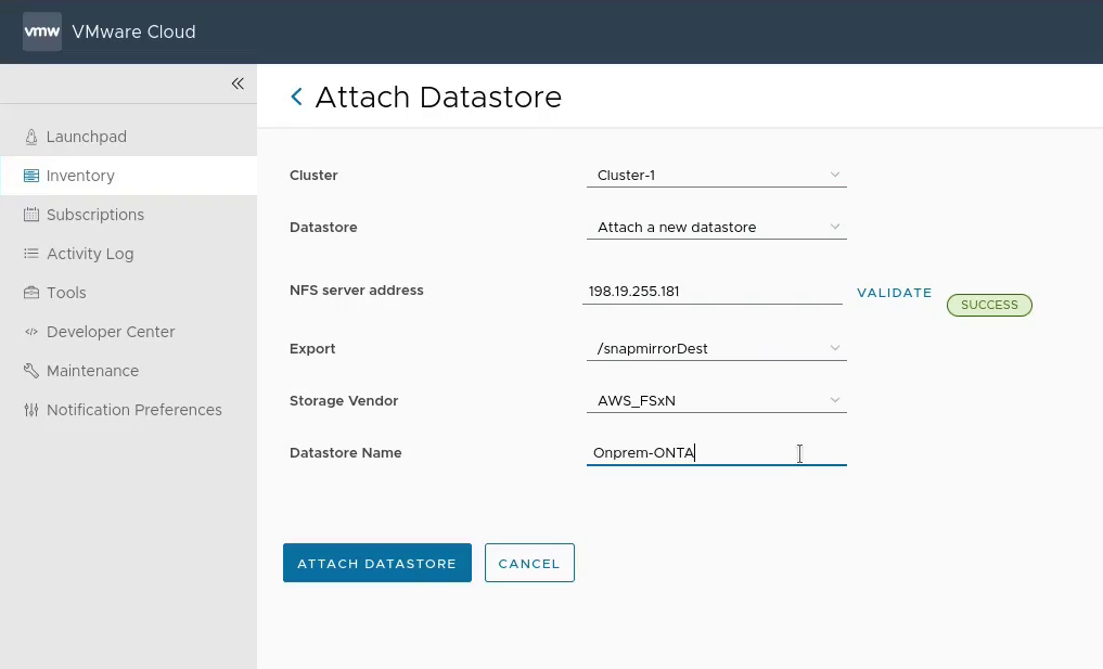
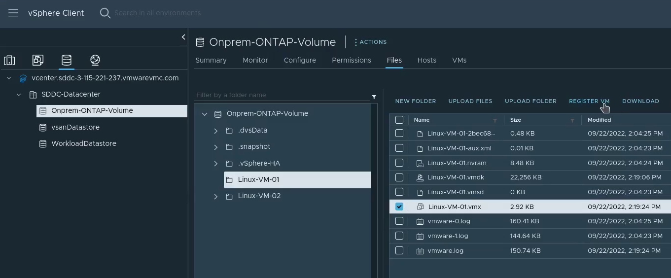
Step 9: [VMC] Import the VMs into vCenter in VMware Cloud on AWS
This can be done manually as per the screenshot below, or automated with a script
Importing using a Python script (initial release – may have rough edges): https://github.com/jonas-werner/vmware-vm-import-from-datastore/blob/main/registerVm.py

Video on how to use the script can be found here:
Step 10: [VMC] Configure the VM network prior to powering on

Wrap-up
That’s all there is to migrating VMs using SnapMirror between on-prem VMware and VMware Cloud on AWS environments. Hopefully this has been useful. Thank you for reading!